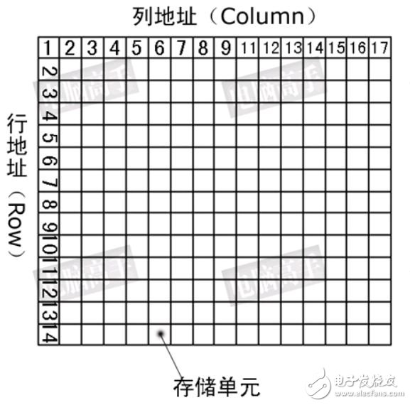
Before introducing SDRAM circuit design, understand the addressing principle of SDRAM. Inside the SDRAM is a storage array, which can be imagined as a table. Just like the retrieval principle of the table, you can specify the row and then specify the column to find the required storage unit. This is the basic principle of memory chip addressing. This form is called a logical bank. Due to technology, cost and other reasons, it is impossible to make only a full-capacity bank, and due to the limitation of SDRAM working principle, a single bank will cause very serious addressing conflicts and greatly reduce memory efficiency, so it is divided into multiple banks in SDRAM. The current SDRAM is basically 4 banks. The storage array is shown in Figure 1:

Figure 1 Schematic diagram of SDRAM storage array

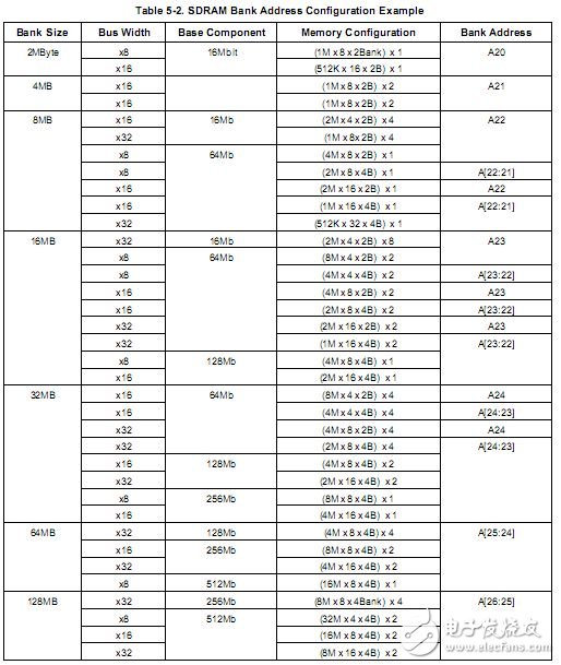
Figure 2 SDRAM pin configuration scheme
Figure 2 shows the SDRAM bank address configuration scheme provided by the S3C2440A manual. The SDRAM used in the maintenance system is HY57V561620FTP-H. Its specification is 4*4M*16bit (two slices are used to configure the 32-bit bus width), BANK size It is 4M*16=64MB, the bus width is 32 bits, the device size is 4*BANK size=256Mb, and the register configuration is (4M*16*4B)*2. According to Figure 2, the BANK address pin on the SDRAM (BA) [1:0]) is connected to A[25:24] of S3C2440.

Figure 3 S3C2440A control address bus connection
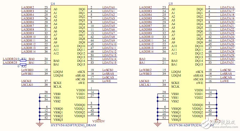
Figure 3 shows the register control address bus connection. We use two SDRAMs to configure the 32-bit bus width, so A[12:0] on the SDRAM is connected to the A[14:2] pins of the S3C2440. The specific SDRAM circuit connection is shown in Figure 4:

Figure 4 SDRAM circuit connection diagram
The address pins of the SDRAM are multiplexed. When reading and writing SDRAM memory cells, the operation process is to input the read and write addresses into the chip twice, each time sent by the same group address line, and sent to the chip twice. The addresses are called row address and column address, respectively, which are latched into the row address latch and column address latch inside the chip. Below is a partial signal of the chip
Rotary encoders are used as sensors for angle,position,speed and acceleration. We can offer incremental encoders and absolute encoders.

Absolute Encoder,Custom Encoder On Motor,Custom Optical Encoders,High Resolution Encoder
Yuheng Optics Co., Ltd.(Changchun) , https://www.yuhengcoder.com