Introduction: This design example provides two simple, inexpensive drivers for headphones and audio lines that are designed for electric guitars and violins, but are also suitable for many other applications.
The popular 555 timer can be used as a PWM/D class amplifier for musical instruments or other applications. It can operate from a supply voltage range of 4.5V to 16V and can output a drive current of 200mA. The audio signal is sent to the CV (Control Voltage) pin of the 555 timer.
This design example provides two simple, inexpensive drivers for headphones and audio lines, as shown in Figure 1 and Figure 2, respectively. These two drives are designed for electric guitars and violins, but are also suitable for many other applications. For such simple applications, noise and total harmonic distortion (THD) are not important considerations, so these two values ​​are not measured.

Figure 1: Headphone and audio line drivers with op amps and NE555 timers. It is also possible to use a CMOS version (such as LMC555) but with a lower output current. The advantage is that the operating frequency is higher.
The following are some design considerations:
◠The input resistance of the CV pin is approximately 3kΩ. In most audio applications, some kind of audio preamplifier/buffer is required.
â— CV requires a very large input audio signal. The required amplitude depends on the power of the 555 timer and the required output audio power.
â— The 555 timer is used as an oscillator and is modulated by a lower frequency audio signal applied to the CV. The oscillating frequency should preferably be at least 10 times the maximum desired audio frequency. For audio applications, the frequency should be between 60kHz and 200kHz. This simplifies the filtering of high frequency noise generated by the 555 timer and maintains high switching efficiency.
â— Pay attention to RF emissions. A first-order low-pass filter should be placed at least between the output of the 555 timer and the speaker or headphone. If the cable is long, the cable parasitic capacitance (preferably twisted pair) should be considered.
With the formula Av1 = 1 + R6 / R12, the first stage gain is set to about 11 by R6 and R12.
The frequency of the timer when there is no analog signal input on the CV depends on the values ​​of R7, R8 and C5. The standard calculation formula is as follows:
f=1.44/((R7+2R8)&TImes;C5)(Hz)
The output signal of the NE555 is transmitted to the connectors OUT1, OUT2 and OUT3. R9, C7 and load can be used as low-pass filters to filter out the high-frequency components produced by the timer. If unfiltered, these components can cause radiation, causing problems with sensitive electronic devices around the amplifier. The cutoff frequency of the filter should be minimized and headphones with higher resistance should be selected.
Junction Field Effect Transistor (JFET) version
The circuit can also use field effect transistors or bipolar transistors to achieve high input impedance and amplify the audio signal before the NE555.
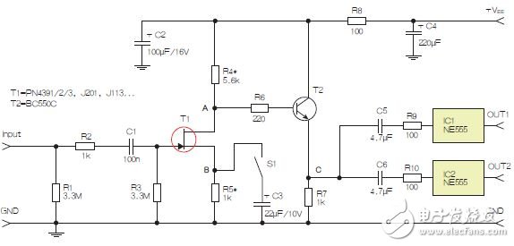
The input stage of the circuit is built around JFET T1. Resistors R4* and R5* should have a minimum applicable value. They should produce a certain gain and have a low output impedance to drive the 555 timer. In the absence of an input signal, the DC voltage between point A and point B is approximately VEE/3. This circuit is simpler than the circuit shown in Figure 1, but it may be necessary to adjust R4* and R5* depending on the transistor T1 selected and the voltage gain required for the first stage. The problem here is that the difference in JFET parameters for a given type may exceed 4:1. When switch S1 is closed, the gain of T1 is set to the maximum value.
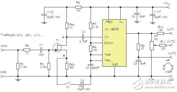
Figure 2: Headphone/line driver with JFET input and NE555.
The bipolar transistor T2 can increase the driving capability of the JFET. In addition, it also supports the use of higher R4* values, which increases the voltage gain of T1.
The circuit shown in Figure 3 uses two 555 timers operating at different frequencies to achieve different sound effects.
in conclusion
This type of circuit can operate over the entire voltage range of the 555 timer (4.5V to 16V), but higher +VEE (such as 12V to 16V) is preferred. This will produce more output power, and most op amps and JFETs will perform better in this voltage range.
This type of circuit can drive high-impedance speakers and headphones – more than 24Ω is preferred. In either case, it is better to keep the peak output current of the 555 timer below 150mA. This will keep the chip's power consumption within an acceptable level. If the output current is much higher than 100mA, the voltage drop of the 555 timer output transistor will increase rapidly.
[Recommended article] NE555 application circuit complete works
FFG-PG Glass Fiber Cloth is made by Braided non-alkali Glass Fiber or High Bulk Glass Fiber
Product introduce:
Glass fiber reinforced material woven cloth is material of hull, storage tank, cooling tower, ship, vehicle, pot and architectural structure.Glass fiber cloth is mainly used in industries for heat insulation, fire proof and flame resistance. It can absorb a lot heat and prevent the flame through the cloth when suffer flame burning, and make the air insulating.
The bulk fabric cloth have the same effect with glass fiber cloth.
1. Working at -196 degrees C up to 700 degrees C. Weather proof.
2. Very difficult to be sticked by any material.
3. Resistance to chemical corrosion: strong acid and alkali, aqua regia and all kinds of organic solvents.
4. Low friction coefficient.
5. Light Transmittance: 6~13 %.
6. High insulation property,anti-UV,anti-static.
7. High strength and very good mechanical performance.
Standard Sepcifications:
PART NO. Material THICKNESS/mm GRAIN/mm WIDTH/mm WEIGHT g/㎡
FFG-PG 02 Alkali-free glass fiber 0.2 plain 1.27 180
FFG-PG 04 Alkali-free glass fiber 0.4 broken twill 1.0 1.25 1.5 1.8 430
FFG-PG 05 Alkali-free glass fiber 0.5 satin 1 500
FFG-PG 06 Alkali-free glass fiber 0.6 satin/twill 1 660
FFG-PG 08 Alkali-free glass fiber 0.8 satin 1 1.2 1.25 1.5 840
FFG-PG 10 Alkali-free glass fiber 1.0 satin 1 1.2 1.25 1.5 1050
FFG-PG 15 Alkali-free glass fiber 1.5 satin 1 1.2 1.25 1.5 1500
FFG-PG/H 08 (Bulked Fiber) (High Bulked Glass Fiber) 0.8 plain 1 1.25 1.5 1.8 620
FFG-PG/H 10 (Bulked Fiber) (High Bulked Glass Fiber) 1 plain 1 1.25 1.5 1.8 800
FFG-PG/H 15 (Bulked Fiber) (High Bulked Glass Fiber) 1.5 plain 1.25 1.5 1.8 1000
FFG-PG /H 20 (Bulked Fiber) (High Bulked Glass Fiber) 2 plain 1 1.25 1.5 1.8 1300
FFG-PG/H 30 (Bulked Fiber) (High Bulked Glass Fiber) 3 plain 1 1.25 1.5 1.8 2000
Product picture:

Fire Resistant Fiber Cloth,Insulation Glass Fiber Cloth,Fiberglass Insulation Fabric Cloth,Aluminium Foil Glass Fiber Cloth
KEYUACE Materials Co., Ltd. , https://www.insulationtubing.com