Summary:
This article presents the design and implementation of a phase shift controller based on the PSoC 3 platform using Cypress components. The system utilizes CapSense technology for input signal detection, enabling digital phase modulation through the PSoC to control power output efficiently. It also provides multiple key input signals to meet various user application needs, offering a more reliable and flexible solution compared to traditional methods.
Introduction:
In industrial applications, power regulation is typically achieved using thyristor-based phase control, which adjusts the conduction angle of AC voltage to regulate power delivered to the load. However, this method often relies on potentiometers, which suffer from mechanical wear, noise, and limited lifespan. This design replaces the mechanical adjustment with a digital solution using PSoC technology, integrating CapSense and buttons as input interfaces. By leveraging digital phase modulation, the system eliminates the drawbacks of traditional potentiometer-based controls, enhancing reliability and performance.
PSoC Overview:
PSoC (Programmable System-on-Chip) is a highly integrated microcontroller developed by Cypress Semiconductor. It combines an 8-bit microprocessor, programmable analog and digital modules, and a constant current source (IDAC), along with peripherals such as I2C, Flash, SRAM, and more. As shown in Figure 1, the PSoC architecture allows for flexible implementation of embedded system functions. Cypress has also developed a wide range of user modules, including operational amplifiers, ADC/DACs, timers, comparators, filters, and touch sensing modules. These modules simplify design by handling internal configuration and API functions, making it easy for developers to implement complex functionalities without deep hardware knowledge.
System Principle:
The AC signal is isolated from the PSoC using optocoupling, and the zero-crossing point of the AC waveform is detected and sent to the PSoC via this isolation. Using an interrupt-driven approach, the system synchronizes with each AC cycle, and the internal timer of the PSoC determines the initial phase. Based on this, a trigger pulse is generated to control the phase shift of the AC output, thereby adjusting the power delivered to the load. A Nokia 5110 LCD is used to display parameters like the phase shift angle. Figure 1 illustrates the main circuit structure.
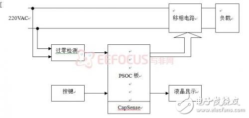
Figure 1. Main Circuit Block Diagram
Program Design:
2.1 Scheme 1
This scheme uses an ASIC designed for AC control, manufactured using CMOS technology and controlled by external AC pulses. It offers various control methods to suit different user requirements, allowing phase shifts between 0° and 180°. However, this approach increases the cost of external components, reduces flexibility, and is more prone to failure due to its fixed nature.
2.2 Scheme 2
This design implements phase modulation through software control. The CPU detects the zero-crossing point of the AC signal using a peripheral circuit and generates an accurate synchronization trigger pulse after processing. This method offers greater flexibility, higher precision, and easier implementation of closed-loop control. It also supports better scalability and adaptability for future expansions or modifications.
75inch Multimedia All-in-One PC
LCD touch all-in-one machine,Wall Mount Touch Screen Monitor,Smart interactive touch electronic board
Jiangsu Qilong Electronic Technology Co., Ltd. , https://www.qilongtouch.com