This article takes Siemens S7-200plc as an example to illustrate the installation, inspection and maintenance of programmable controllers. Of course, the content described in this chapter has certain guiding significance for most PLCs.
It should be especially noted that when installing and removing the various modules and related equipment of the programmable controller, the power must first be turned off. Failure to do so may result in damage to the equipment and personal injury.
1. General Guide for Programmable Controller Installation The following describes the general method of PLC design and installation:
• When wiring the PLC, make sure that all electrical appliances meet the national and regional electrical standards. Keep in touch with the authority of the region to determine which standards meet your specific needs.
• Use the wires correctly. The PLC module uses a wire of l.50mm2~0.50mm2.
• Do not overtighten the connector screws. Do not exceed a maximum torque of 0.36 Nm (Newton meters).
• Try to use short wires (up to 500 m shielded cable, or 300 m unshielded wire). Use the wires as far as possible. Use a neutral or common wire to pair with a hot wire or signal wire.
• Separate the AC line and the high current fast switching DC line from the low current signal line.
• Correctly identify and divide the terminals of the PLC module and leave the buffer coils on the line.
• Install a suitable surge suppression device for lightning surges.
• Do not use an external power supply in parallel with the DC output point as an output load, which may cause a reverse current to impinge on the output unless a diode or other isolation barrier is used during installation.
• The control device may malfunction under unsafe conditions, resulting in misoperation of the controlled device. Such malfunctions can cause serious personal injury and severe damage to the equipment. Consider using an emergency shutdown function independent of the programmable controller, an electromechanical overload protection device, or other redundant protection.
2. Grounding and Circuit Reference Point Guidelines when Using Isolated Circuits
(1) The grounding and circuit reference points when using an isolated circuit should follow the following points:
• A reference point (0V) should be selected for each mounting circuit. These different reference points may be connected together. This connection may cause unexpected currents that can cause logic errors or damage the circuit. The reason for generating different reference potentials is often due to the fact that the grounding points are too far apart on the physical area. When devices that are far apart are connected by communication cables or sensors, current generated between the cable and the ground flows through the entire circuit. Even within a short distance, the load current of a large device can change between it and the ground potential, or directly generate an unpredictable current through electromagnetic action. Power supplies that do not correctly select the reference point may have devastating currents in the circuit between them, causing damage to the device.
• When connecting several CPUs with different ground potentials to a network, an isolated RS-485 repeater should be used.
• PLC products have installed isolation components at specific points to prevent unwanted currents during installation. When you are planning to install, you should consider where these isolation components are and where they are not. At the same time, you should also consider the isolation between the relevant power supplies and the isolation of other equipment, as well as where the reference points of the relevant power supply are.
• It is best to choose a ground reference point and use isolation components to destroy unwanted current loops that can cause unpredictable currents. Keep in mind that new circuit reference points may be introduced in temporary connections, such as when a programming device is connected to the CPU.
• When grounding in the field, be sure to pay attention to the safety of the grounding and operate the isolation protection device correctly.
• In most installations, optimal noise suppression can be achieved by connecting the sensor's power M terminal to ground.
The above is an overview of the isolation characteristics of PLC0, but some features may vary for a particular product. Please refer to each PLC system manual to find out which isolation components and their isolation levels are included in the circuit of your product. Isolation components rated less than 1500V AC can only be used as functional isolation and not as a safety barrier.
(2) Isolation characteristics of PLC The isolation characteristics of the following PLCs can be used as a reference for use.
• The CPU logic reference point is similar to the M point provided by the DC sensor.
• The CPU logic reference point is similar to the M point provided by the CPU input power supply powered by DC power.
• The CPU communication port and the CPU logic port (except the DP port) have the same reference point.
• The analog inputs and outputs are not isolated from the CPU logic. The analog inputs use differential inputs and provide a low-voltage common mode filter circuit.
• The isolation between the logic circuit and ground is 500V AC.
• The isolation between the DC digital inputs and outputs and the CPU logic is 500V AC.
• The isolation between the points of the DC digital I/O group is 500V AC.
• The isolation between the relay output, AC output and input and the CPU logic is 1500VAC.
• The isolation between the points of the relay output group is 1500V AC.
• The isolation between the AC power cord and neutral and ground, CPU logic, and all l/O is 1500V AC.
3. Power supply installation
(1) AC input PLC installation guide The following items are general guidelines for AC AC wiring installation.
• Use a single-pole switch to isolate the power supply from the CPU, all input circuits, and output (load) circuitry.
• Use an overcurrent protection device to protect the CPU's power, output points, and input points. It is also possible to add a fuse to each output point for a wider range of protection.
• When you use the Micro PLC 24V DC sensor power supply, you can cancel the external overcurrent protection at the input point because the sensor power supply has short-circuit protection.
• Connect all ground terminals of the PLC to the nearest ground point for best interference immunity. It is recommended that all wires be connected to separate conductive points (also known as one-point grounding) using a 1.50mm2 wire.
• The unit's DC sensor power supply can be used to power the input and expansion DC inputs of the unit and the extended relay coil. This sensor power supply has short-circuit protection.
• In most installations, optimal noise suppression can be achieved by connecting the sensor's power M terminal to ground.
(2) DC Input PLC Installation Guide The following items are general guidelines for DC isolated installation wiring.
• Use a single-pole switch to isolate the power supply from the CPU, all input circuits, and output (load) circuits.
• Use overcurrent protection devices to protect CPU power, output points, and input points. It is also possible to add a fuse to each output point for overcurrent protection. When using the Micro 24V DC sensor power supply, external overcurrent protection at the input point can be eliminated because the sensor power supply has a current limit function inside.
• Ensure that the DC power supply has sufficient shock resistance to maintain a stable voltage during sudden load changes, requiring an external capacitor.
• In most applications, all DC power supplies are connected to ground for optimum noise rejection. A resistor and capacitor parallel circuit is connected between the common end of the ungrounded DC power supply and the protection ground. The resistors provide an electrostatic discharge path and the capacitors provide high frequency noise paths. Typical values ​​are IM Ω and 4700pF.
• Connect all ground terminals of the PLC to the nearest ground point for best interference immunity. It is recommended that all ground terminals be connected to separate conductive points (also known as one point ground) using a 1.5mm2 wire.
• Safe electrical isolation must be provided between the 24V DC power circuit and the equipment, and between the 120/230VAC power supply and the hazardous environment.
4. Suppress the use of the circuit
(1) General guidance for suppression circuit use A suppression circuit is added to the inductive load to suppress an increase in voltage when the power is turned off. The following method can be used to design a specific suppression circuit. The effectiveness of the design depends on the actual application, so the parameters must be adjusted to suit the specific application. All device parameters are to be protected against the actual application.
(2) DC transistor output module protection
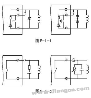
The PLC DC transistor output contains a Zener diode that can accommodate a variety of installations. For inductive loads with large inductance or frequent switching, an external suppression diode can also be used to prevent breakdown of the internal diode.
It is also possible to use an external Zener diode to form a suppression circuit. If the applied DC voltage is 24V, the breakdown voltage of the selected Zener diode should be 8.2V and the power is 5W.
Thus, when the transistor is turned off from turn-on, since the freewheeling diode provides a current path for the release of the inductor energy, no high voltage is formed across the inductor. For a suppression circuit including a Zener diode, due to the voltage characteristics of the Zener diode, high voltage generation across the inductor can also be suppressed. Therefore, it will not harm the transistor. See Figure F-1-1. 
(3) Protection of the relay output module There are two main aspects to the protection of the relay output module. One aspect is the protection of the relay contacts so that the inductor does not generate high voltages to the contacts of the relay when the power is turned off. Another aspect is the protection of the power supply so that the power supply that supplies the voltage to the relay is not affected by high voltages. The main way to suppress high voltage is to connect the RC snubber circuit in parallel with the inductive load. In addition to the RC absorption of the AC power supply, the varistor can be connected in parallel to eliminate the voltage shock.
The reference value of the DC load RC suppression circuit is R=12Ω, C=0.5μF/A ~1μF/A.
When the AC load AC voltage is 115V / 230V, for every 10VA static load, the reference value of the RC suppression circuit is R = 0.5 × US Ω, C = 0.002μF / A ~ 0.005μF / A. If the varistor is connected in parallel, the varistor operates at a voltage 20% higher than the normal supply voltage. See Figure F-1-2.
Rectangular I/O Connectors
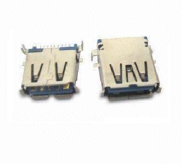
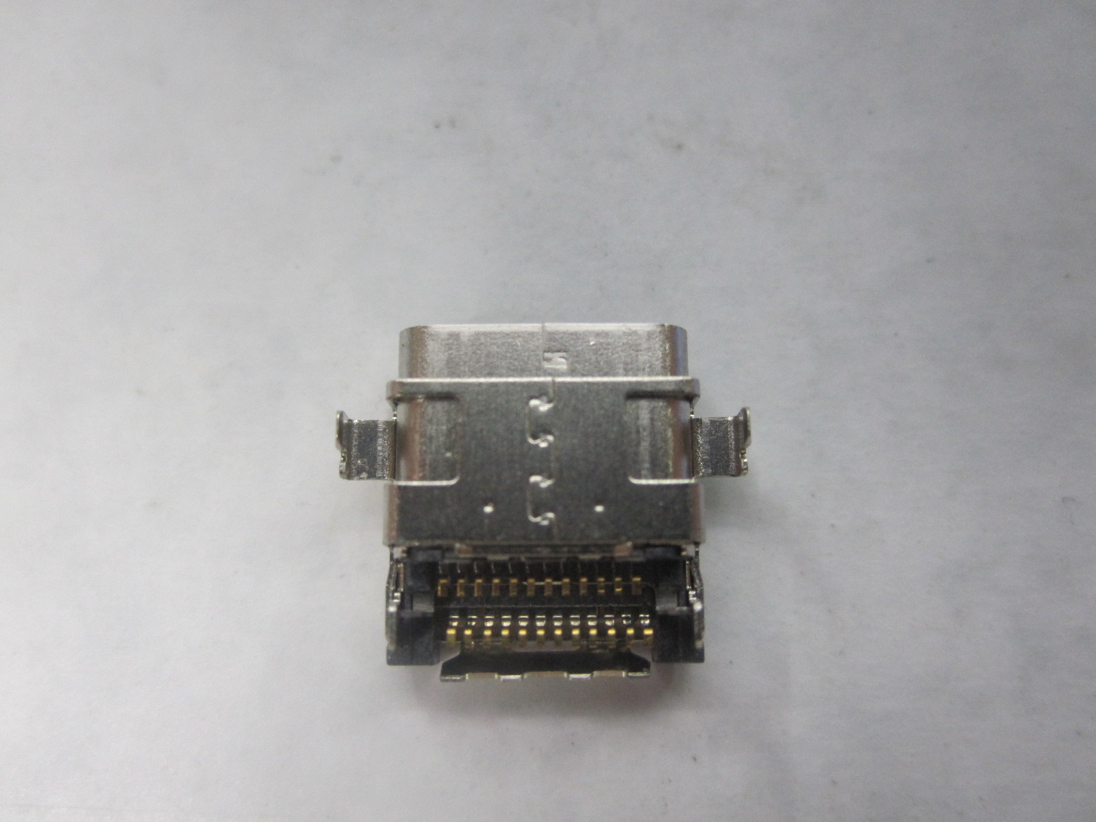
Antenk offers an expansive product line of I/O connectors including USB, HDMI, D-Sub, Modular Jacks, SFP, QSFP+, CXP, iPass+, iPass+ HD and more. In addition to standard I/O connectors and matching cable assemblies.Except a comprehensive range of standard Input/Output connector solutions for high-speed electronic data communication, Antenk engineers can design customized solutions. This extensive selection of I/O connectors and matching cable assemblies includes numerous next-generation solutions.All of our I/O connectors feature a variety of orientation options, as well as PCB and cable mount offerings.
Antenk develop and specify high-performance I/O's throughout a wide variety of industries. These include SAS, SATA, PCIe, HSSG, FIBRE CHANNEL, INFINIBAND, IEC, CEA, IEEE, VESA, USB and many more.
I/O Connectors Application
Consumer / PC Products
Networking / Telecommunications Products
Mobile Products
Industrial Products
Antenk can deliver standard and custom options of the following I/O connectors:
1394 Connector
Centronic Connector
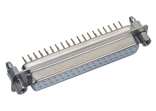
D-Sub Connector
DVI Connector
Display Port Connector
HDMI Connector
Half Pitch SCSI Connectors
USB Connector
V.35 Connector
OBD Connector
I/O Connectors General Specifications


ELECTRICAL CHARACTERISTICS
Contact Current Rating:5Amperes.
Dielectric Withstanding.
Dielectric Withstanding Voltage:AC 1000Vr.m.s.
Insulation Resistance:500 Megohms Minimum at DC500V.
Contact Resistance:25 Milliohms Maximum.
Operating Temperature:-55℃~105℃.

MATERIALS:
Contacts:Brass.
Insulator:PBT,UL94V-O Rated.
Shell:Cold Rolle Steel.
Metal Watertight Frame:PBT,UL94V-0.
O-Ring:Silicone.
NOTE:
Position:09PIN,15PIN,25PIN,37PIN.
Rectangular Connector,Rectangular I Connectors,Rectangular O Connectors,Male Connector Rectangular,I/O Connectors,Input/Output Connectors
ShenZhen Antenk Electronics Co,Ltd , https://www.atkconnectors.com