Abstract: A two-way car alarm is designed. The anti-theft device is composed of a host computer and a remote controller, and adopts a half-duplex communication method. The host can detect multiple trigger sources in the vehicle body, realize automatic anti-theft alarm, and notify the remote controller to perform remote alarm. In addition, the host can also complete the functions of automatic door lock up and down, automatic alarm recovery, and emergency alarm release. Using a custom wireless communication protocol, data transmission is PWM encoded and uses FSK modulation and demodulation. The anti-theft device has the advantages of strong real-time performance, high reliability, and low power consumption.
Keywords: car alarm; half-duplex communication; single chip microcomputer; FSK modulation and demodulation
This article refers to the address: http://
0 Introduction Cars are currently the main means of transportation for human beings and a symbol of modern civilization. The world's annual car sales have reached more than 60 million, and the number of cars has exceeded 500 million. The more cars that are stolen, the more cars are stolen. Therefore, car theft has become an important social issue. It has been listed as four major issues in the development of automotive technology along with safety, environmental protection and energy conservation.
Car anti-theft devices can be divided into three categories according to their structure and function: mechanical, network and electronic. The mechanical anti-theft principle is to lock a structure on the car with a mechanical lock, such as a transmission, a steering wheel, and the like. The anti-theft device is easy to install and cheap, but its volume is large, and the anti-theft device of this type only has no anti-theft alarm and cannot ensure theft prevention. Network-based anti-theft mainly relies on the public network of the society to monitor the driving of vehicles, such as GPS positioning system, GSM or GPRS. The anti-theft device is advanced in technology and powerful in function, but the price is high, the service fee is required, and the communication signal is easily interfered. To reduce the anti-theft performance. The electronic anti-theft device is the most popular anti-theft device in the automobile market. It can realize one-way or even two-way alarm by using the radio transmitting chip in the key to communicate with the ECU in the vehicle body. When the car is invaded by the outside world, the owner of the car can understand the condition of the car through the display on the key that is carried with him, but the disadvantage is that the false alarm rate is high.
This paper presents a two-way electronic car anti-theft system based on single-chip microcomputer, which consists of two parts: the main unit and the remote control. The remote control is carried by the owner of the vehicle, and the host is placed in the vehicle to detect the alarm signal source, and the wireless transceiver module is used for half-duplex communication between the two.
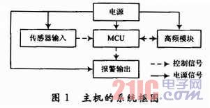
1 Host hardware design The host is placed in the car, consisting of five modules: MCU, power supply, sensor input, high frequency module, and alarm output. The system block diagram is shown in Figure 1. The main controller MCU adopts LPC930, which is used to detect the trigger of the sensor and generate an alarm signal; at the same time, the state of the remote controller is updated to realize the synchronous alarm. Since the sensor input module requires a DC voltage of 12 V and the LPC930 operates between 2.4 and 3.6 V, the SPX1117 regulator is used in the power module to generate a 3.3 V DC voltage. The sound alarm control circuit uses RT0100 circuit. RT0100 is a crystal circuit that can generate a single sound. It is manufactured by CMOS technology and has built-in RC oscillator circuit. The working voltage is 2~5 V and low quiescent current.
1.1 Sensor module design The sensor module includes side gate detection circuit and vibration detection circuit. When various alarms are triggered, the car horn alarms for 30 s, the direction light flashes, and the vehicle fails to start. After the alarm is completed, the anti-theft system automatically returns to the state before the alarm. If the same sensor is detected continuously in a short time, the anti-theft system will automatically stop the alarm after only 4 minutes of alarm. All detection points are re-detected until other sensors are triggered. At this time, the same sensor is detected to be triggered and alarmed again for 4 min.
1.1.1 Side Door Detection Circuit When the host is in the alarm state, the side door detection circuit is used to detect whether the side door is opened. If the side door is opened for no reason, the host enters an alarm state. The detection circuit is shown in Figure 2. In the figure, point A is connected to the side door, and point B is connected to the single chip microcomputer. When the side gate is closed, point B is charged to a high level because diode D2 is reversed. When the side door is opened, point A becomes low level, diode D2 is turned on, relay switch is grounded, RC circuit composed of C1 and R2 is rapidly discharged, point B is pulled low, and a low level signal is generated to the single chip microcomputer. The single chip microcomputer controls the alarm output circuit alarm.
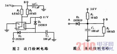
C2 is used to filter low-level glitch pulses to avoid system malfunction. Diode D1 and the relay coil form a bleeder circuit. When the side gate is closed, the remaining charge is discharged through D1 due to the inductance of the relay coil.
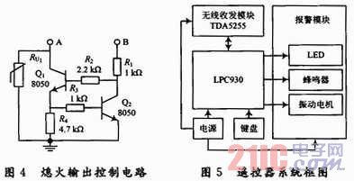
1.1.2 Vibration detection circuit When the host is in the warning state, the vibration detection circuit is used to detect whether the external interference causes the body damage. If the external body vibration causes the body vibration to exceed the limit that the body can withstand, the host enters the alarm state. The circuit diagram is shown in Figure 3. The point A is connected to the vibration detecting sensor, and the point B is connected to the single chip microcomputer. When vibration is detected, A goes low, D1 turns on, and the RC circuit composed of C1 and R2 is rapidly discharged through D1, causing point B to quickly go low. The voltage across C1 cannot be hopped, so this feature is used to filter the low-level glitch generated by the vibration to ensure accurate detection of the vibration hopping signal.
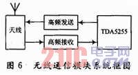
1.2 Alarm output module In addition to the simple sound and light alarm of the horn and the light, the alarm output module also adopts the flameout output control circuit. When the host is in an alarm state, the vehicle is turned off and cannot be started. The circuit diagram is shown in Figure 4, where point A is connected to the flameout output controller, and point B is connected to the microcontroller. When the MCU outputs a high level, the transistor Q1 is turned on, and the A point becomes a high level, and a flameout output signal is generated, and the car cannot be started. Transistor Q2 acts as a shunt protection. When the emitter current of the transistor Q1 exceeds the upper limit, Q2 will be automatically turned on to prevent the Q1 from being damaged due to overcurrent. The varistor RU1 protects Q1 and Q2. When the collector voltage of Q1 does not exceed the upper limit, RU1 will not conduct. However, when Q1 is overvoltage, RU1 is automatically turned on to avoid damage of Q1 during overvoltage.
2 Remote control hardware design The remote control part is composed of MCU, wireless transceiver module, power supply, keyboard and alarm module. The LPC930 is used as a core device to control the operation of each module around it. The wireless transceiver module with TDA5255 as the core receives the data transmitted from the host and forwards it to the LPC930 for processing. The system block diagram of the remote control part is shown in Figure 5.
The wireless transceiver module consists of four parts: antenna, high frequency transmission, high frequency reception and TDA5255. The TDA5255 chip is a powerful low-power FSK/ASK single-chip transceiver chip manufactured by Infineon, Germany. It operates in the 433-435 MHz band and has FSK/ASK modulation and demodulation functions. High integration, complete VCO (voltage controlled oscillator) and PLL (phase locked loop) synthesizer, FSK modulator, RSSI limiter, FSK demodulator, data filter, data splitter, etc., reducing the periphery Circuit design. More importantly, the chip has a power-saving mode function, and the power-saving mode can be set in different ways to meet the low power consumption requirements of the remote controller. The system block diagram of the module is shown in Figure 6.
3 system software design
3.1 Host software design The software part of the host mainly includes wireless data transmission, data processing and backhaul, sensor detection, alarm output and backhaul. It has more than 20 kinds of status and functions to be processed, and real-time. Sex, can have good interaction with the remote control, use two variables STATUS and D-STATUS to store the state of the system and alarm respectively, jump according to the state, the overall flow block diagram shown in Figure 7.
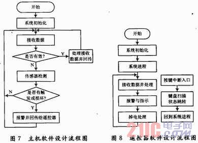
3.2 Remote control software design The remote control software is designed with the button as the first response, and the data reception is the second response. In addition to the functions of data transmission, alarm, button defense, release, etc., music generation and low voltage detection are also required. Additional features such as low power control and signal strength detection. The software design flow chart is shown in Figure 8.
4 Conclusion This system uses the single-chip microcomputer as the main control, adopts a custom communication protocol, realizes the half-duplex communication between the host and the remote controller, thus achieving the function of anti-theft alarm. The remote controller controls the state of the host, and can synchronize alarm with the host; the host can detect multiple trigger sources to realize the remote alarm of the host itself and the remote controller, and can complete the automatic locking of the door set by the remote controller, automatic alarm recovery, emergency alarm release, etc. Features. After testing, the system has the characteristics of strong real-time performance, high reliability and low power consumption.
The most comprehensive introduction of LED PCB
In China, there are many PCB manufacturers and suppliers. Jinghongyi PCB is one of the LED PCB Board manufacturers. We only provide LED PCB fabrication services. LED PCB design is not our specialty and business scope.
LED PCB Board Introduction
LED PCB has many other names, such as LED PCB board, LED circuit, LED Circuit Board, led printed circuit boards, PCB board for LED.
In a sense, LED PCB and Aluminum PCB belong to the same kind of PCB products, because their uses and materials are mostly the same.
With the popularization and widespread use of industrial lighting and civil lighting, whether outdoor or indoor, family or commercial buildings and factories, lighting provides the guarantee of its normal operation.
Of course, nowadays, with the development of human society, environmental pollution has become a difficult problem in the world. In order to reduce the consumption of coal, such as coal used for power generation in thermal power plants, coal combustion pollutes the atmosphere very seriously. In order to save energy and protect the environment, LED lights and previous lighting methods have great advantages, except for energy. Besides providing brighter lights, it also contributes to environmental protection.
LED PCB Meaning
LED circuit board is a kind of Printed Circuit Board.

LED PCB Board manufactureing
Both LED aluminium PCB and FR-4 fiberglass circuit board belong to PCB. To say differently, only compare LED aluminium substrate with FR-4 fiberglass circuit board.
LED aluminium substrate is printed on the surface of aluminium material with better thermal conductivity, and then weld electronic components on it.
In electronics, an LED circuit or LED driver is an electrical circuit used to power a light-emitting diode (LED). The circuit must provide sufficient current to light the LED at the required brightness, but must limit the current to prevent damaging the LED.

The voltage drop across an LED is approximately constant over a wide range of operating current; therefore, a small increase in applied voltage greatly increases the current.
Very simple circuits are used for low-power indicator LEDs. More complex, current source circuits are required when driving high-power LEDs for illumination to achieve correct current regulation.
An LED PCB board tends to generate a high volume of heat, making it difficult to cool via traditional means.
LED PCB Board Material - LED PCB raw material, LED bulb PCB raw material, LED strip PCB material
Metal core PCBs are often chosen for LED applications because they have enhanced heat dissipation capabilities. In particular, aluminium is usually used to make circuit boards for LED lamps. Aluminum substrates usually consist of thin layers of thermal conductive dielectrics that can be transported and have much more efficient heat dissipation than conventional rigid PCBs.
Compared with other electronic components, LED generates more heat, which requires PCB to heat very well. For this special feature, Metal Core PCB is often used in LED circuit boards, especially Aluminum Core PCB .
LED Lighting PCB Assembly
Seeking LED PCB and Assembly? LED PCB Manufacturing and assembly; Led board made based on your PCB files. Turn-key services; 100% inspection.

Applications of LED PCB
PCB LED lights can be incorporated into numerous lighting applications due to their combination of excellent energy efficiency, low cost and maximum design flexibility.
- Automotive headlights
- Airport runway landing lights
- Lighting used in military field
- Street lighting
- Highway tunnel lighting
- Photovoltaic (solar) lighting
- Flashlights and lanterns
- Traffic and signal lighting
- Lighting in hospital operating rooms
- High growth plant lighting
- Highway tunnel lighting
- Solar power products

If you have any questions about LED PCB Board, Please feel free to send us email. If you have final Gerber for production, welcome your inquiry.
Additional Information
Aluminum PCB for LED Light/Lamp/Tube
Aluminum PCB for LED
Aluminium Base LED PCB
LED Metal Core PCB
Metal Core PCB for LED
PCB industry cut into LED PCB heat sink aluminum substrate
Double Sided Aluminum PCB
LED PCB
LED PCB,LED Circuit Board,LED PCB Board,LED Printed Circuit Board
JingHongYi PCB (HK) Co., Limited , http://www.pcbjhy.com