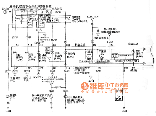
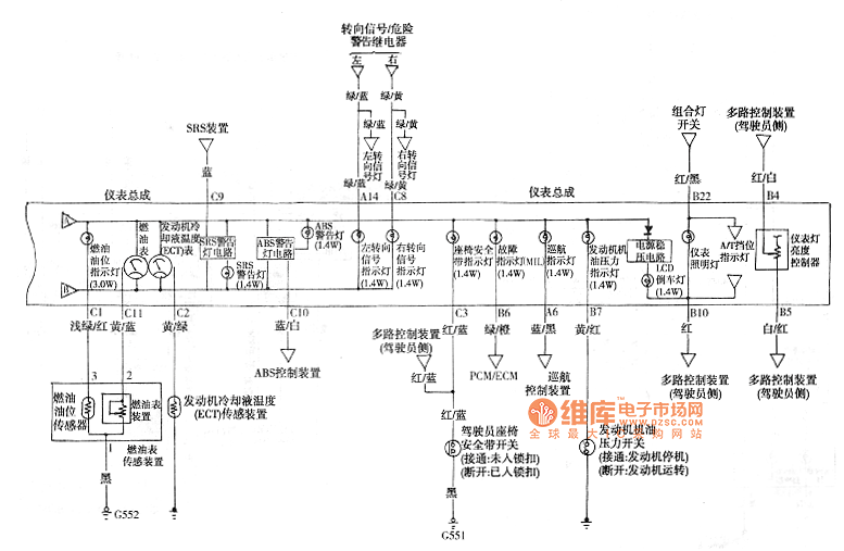
Accord combination meter circuit diagram as shown
Ceramics Base Copper-clad Laminates
What is a High Frequency Pcb?
LED is the English abbreviation of light-emitting diode. Its basic structure is a piece of electroluminescent semiconductor material origin electronics IC, which is cured on the bracket with silver glue or white glue, and then connects the chip and the circuit board with silver or gold wire, and then around It is sealed with epoxy resin to protect the inner core wire, and finally the shell is installed, so the layer LED Based Night Lamp has good seismic performance.
The structure and working principle of the led lamp circuit board are: the core part of the light-emitting diode is a wafer composed of p-type semiconductor and n-type semiconductor, and there is a transition layer between p-type semiconductor and n-type semiconductor, which is called p-n junction. In the PN junction of certain semiconductor materials, when the injected minority carriers and the majority carriers recombine, the excess energy is released in the form of light, thereby directly converting electrical energy into light energy. With reverse voltage applied to the PN junction, it is difficult to inject minority carriers, so it does not emit light. This kind of diode made by injection electroluminescence principle is called light-emitting diode, commonly known as LED. When it is in a positive working state (that is, a positive voltage is applied to both ends), when the current flows from the LED anode to the cathode, the semiconductor crystal emits light of different colors from ultraviolet to infrared. The intensity of the light is related to the current.
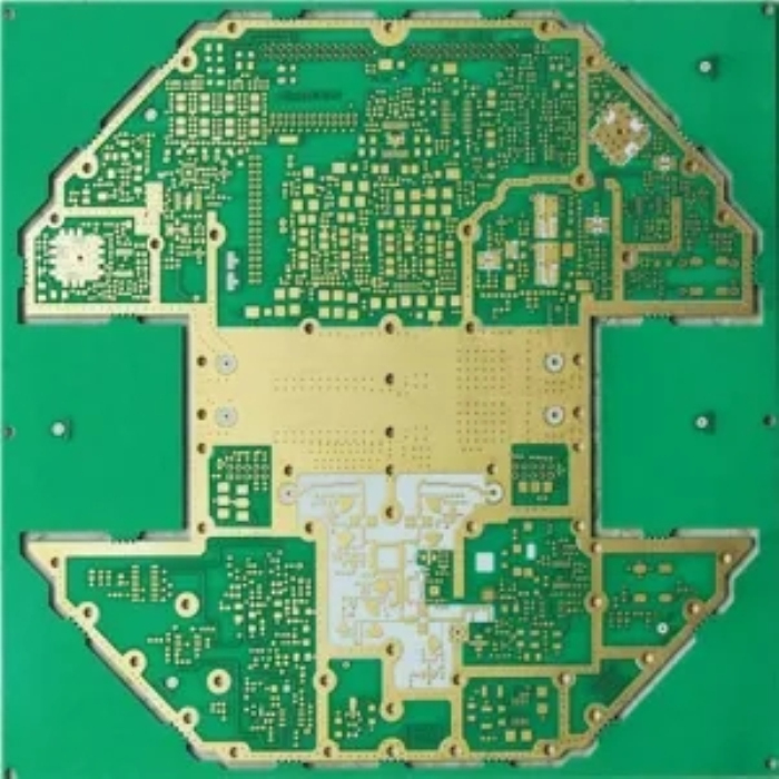
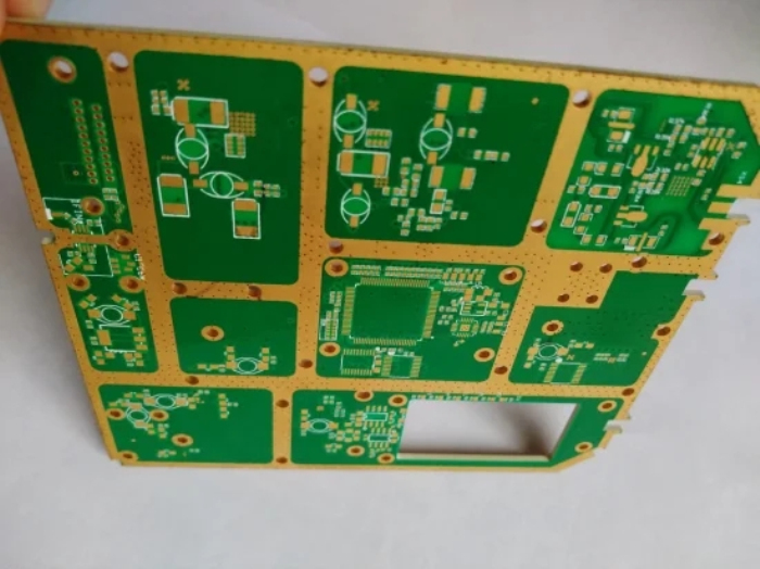
â‘ Judgment of the direction of the lamp: the front is facing up, and the side with the black rectangle is the negative end;
â‘¡The direction of the circuit board: the front is facing up, and the end with two internal and external wiring ports is the upper left corner;
③Judgment of the direction of the lamp in the circuit board: starting from the lamp on the upper left (clockwise rotation), the sequence is negative plus → plus minus → minus plus → plus and minus;
â‘£ Welding: Weld carefully to ensure that every solder joint is full, clean, and there is no false soldering or missing soldering.
2. Self-inspection
After the soldering is completed, first check whether the solder joints have false soldering, missing soldering, etc., and then touch the positive and negative ends of the circuit board with a multimeter (outer positive and inner negative), check whether the four LED lights are on at the same time, and perform Modify until all functions of PCBA can work normally.
3. Mutual inspection
After the self-inspection, it must be handed over to the person in charge for inspection, and can flow into the next process with the consent of the person in charge.
4. Cleaning
Brush the PCBA with 95% alcohol to remove the residue on the board and keep the circuit board clean.
5. Friction
Remove the LED light circuit boards from the entire board one by one, use fine sandpaper (coarse sandpaper if necessary, but with the consent of the person in charge) to grind off the burrs on the side of the circuit board, so that the circuit board can be placed in the holder flatly Inside (the degree of friction depends on the model of the holder).
6. Cleaning
Clean the circuit board with 95% alcohol to remove the dust left on the circuit board when rubbed.
7. Wiring
Connect the circuit board with a thin blue wire and a thin black wire. The connection point near the inner circle is negative, and the black line is connected. The connection point near the outer circle is positive, and the red line is connected. When wiring, make sure that the wire is connected from the reverse side to the front side.
8. Self-inspection
To check the wiring, it is required that each wire pass through the pad, and the length of the wires on both sides of the pad should be as short as possible on the surface, and the thin wires will not be broken or loose when pulled lightly.
9. Mutual inspection
After the self-inspection, it must be handed over to the person in charge for inspection, and can flow into the next process with the consent of the person in charge.
10. Aging
Separate the wires on part of the circuit board according to the blue and black wires, and energize each LED lamp with a current of 15mA (the voltage is constant at 3.7V, and the current is multiplied). The aging time is generally 8 hours.
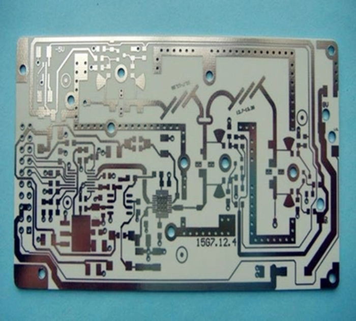
high frequency pcb vias, high frequency signal integrity pcb,high frequency signal pcb,high frequency pcb application
HAODA ELECTRONIC CO.,LIMITED , https://www.pcbhdi.com