The era of Industry 4.0 has arrived. The CAN bus application based on autonomous priority arbitration and error retransmission mechanism is very extensive. The same various bus faults and problems are also very troublesome for engineers. In fact, the best solution is that the product design should be relatively rigorous in the early stage. Today, we are mainly familiar with the common interface and wiring specifications of the CAN bus.
With the increasing application of CAN bus technology, not only automotive electronics and rail transit, but also medical equipment, industrial control, smart home and robot network interconnection, etc., of course, our engineers are also troubled by various wonderful bus problems. In the later stage, it is better to avoid problems in the early stage.
First, the common CAN bus standard interfaceThe CAN bus interface has been clearly defined in the CIA published standard CIA 303_1, and the well-known interface definitions help to improve the compatibility of its own products and other devices.
1. DB_9 terminal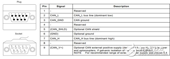
Figure 1 DB_9 interface definition
Figure 1. The most commonly used 9-pin D-Sub connector in the general industry, sub-head and female. It is worth mentioning that pins 6 and 9 are also defined in the standard. 9 is defined as transceiver/light. The positive power supply of the coupler, but it is often changed in the industrial field. 6 and 9 are also commonly used as input pins for the power supply voltage of CAN devices, but this technique has limitations because the current delivered through the pins is very limited. , refer to the standard CIA 303_1.
2. OPEN_5 terminal
Figure 2 Open_5 interface definition
Figure 2 shows the interface definition in the form of Open_5. If the OPEN_4 terminal is generally used with 1-4pin or 2-5pin, if the Open_3 terminal is used for 2-4pin, it should be selected according to the actual situation.
3. M12 terminal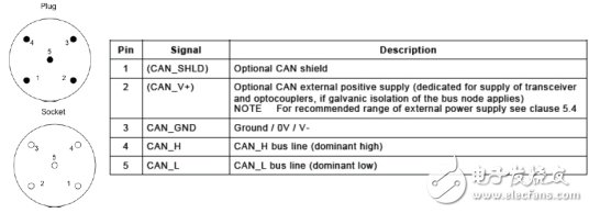
Figure 3 M12 interface definition
Figure 3 is the interface definition of the M12 form. There may be no special points to be noted here. In addition to the 5pin interface, there are 8pin, 9pin, 10pin and 12pin interfaces. The specific definition is not mentioned here. Refer to the standard CIA 303_1. .
Second, CAN bus wiring specificationIf you are a CAN bus entry white, the following bus wiring specification, you may have to collect it, and look at it from time to time when you are networking, I believe it will be very helpful to you.
1. CAN bus wiring form1) "Hand in hand" connection

Figure 4 "Hand in hand" connection
Hand-hand wiring is the most basic way. It should be noted that the resistance and reactance distribution must be reasonable when wiring. It is generally required to have a 120 ohm terminating resistor at both ends, not only single or non-connected.
"T" type connection

Figure 5 "T-type" connection
The wiring method of "T-connection" needs to pay attention to the length of the branch. Generally, when the baud rate is 1M, the branch length should not exceed 0.3m. If you need to increase the branch length, you can reduce the communication speed or use (CANbridge+). The repeater extends the distance. In general, the branch wiring is as shown in Figure 5.

Figure 6 Relationship between branch distance and baud rate
3) Star topology
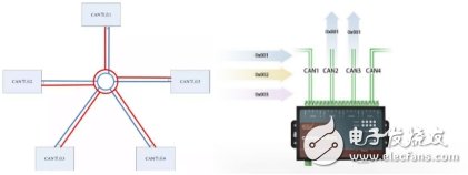
Figure 7 Star topology
For the star topology, it is necessary to pay attention to the matching of the termination resistance of each branch. Generally, the equidistant branch termination resistance R=N (number of branches) *60 can be used. If it is not equidistant, it needs to be matched according to the actual situation. The star network is generally recommended to use the (CANHUB-AS4) hub, which can effectively isolate the interference of the sub-network and extend the communication distance.
2. Network function implementationAfter choosing the form of networking, then we have to consider whether the functions after the actual networking can meet the needs. Then I will share with you through a case.
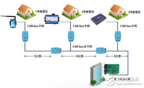
Figure 8 Network diagram
The above case is relatively simple, the central control room is generally controlled by computer, but the interface of the computer is generally PCI/CPCI/USB interface, which needs to be extracted by using the relevant interface conversion card, followed by the relationship between transmission distance and transmission rate, generally following [transmission] Distance (km) = (50000 / baud (byte)) * 0.8], for reference only, depending on the situation, if you want longer transmission distance and transmission rate, the following scheme can provide reference:
1) Add a relay device (Can Bridge+), which generally doubles the transmission distance;
2) Using CAN to fiber optic equipment (CANHub-AF2S2), the fiber has strong anti-interference ability, and the transmission distance is generally twice the transmission distance of CAN;
3) Using CAN to Ethernet (CANET-XE-U), the Ethernet transmission rate is generally 10/100/1000M, reducing signal transmission time.
Now we basically solve the problem of networking form and transmission. You may have overlooked two problems. One is the choice of transmission cable. Is it thick cable, shielded, twisted pair or parallel?
3. Bus network cable selection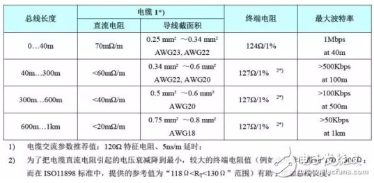
Figure 9 Cable selection and termination resistance matching
I have to say here that many CAN bus engineers who are in contact with me will ignore this cable selection and termination resistance matching problem. For cable selection, many engineers seem to pay more attention to cables. Generally, parallel cables are selected. Shielded cable, although shielded, CAN_H and CAN_L parallel routing does not suppress common mode interference, resulting in bus transmissions always occasionally sending some error frames, resulting in data retransmission, occupying bus resources and other data transmission, Delays in critical data transmission, causing great problems for R&D engineers, resulting in project delays;
Secondly, the influence of the terminating resistor on the bus can not only remember the terminal resistance of 120 ohms, but also should be properly matched according to the choice of different lengths and cables.
Solar Charging Controller,Charge Controller,Solar Controller,Solar Regulator
SUZHOU DEVELPOWER ENERGY EQUIPMENT CO.,LTD , https://www.fisoph-power.com