introduction
This article refers to the address: http://
With the increasing digitization of televisions and the enhancement of functions, TV software upgrades are becoming more and more important, and various TV failures require software upgrades to solve them. At present, the method of upgrading the TV software mainly burns the software into the memory through a special software burner, and then solders the memory to the TV main board; or connects the computer to the TV, and writes the upgrade program to the TV through the computer. Memory. These two TV software upgrade methods have the defects of complicated operation, long time, high cost, and professional knowledge.
System principle
The principle of the portable TV software upgrade system is shown in Figure 1. The TV software upgrade system is a system that can be operated independently based on the single chip W79E632. Firstly, the system is upgraded as a slave to receive the upgrade program data sent by the computer system and stored, and then the upgrade system is used as a host to send the stored upgrade program data to the television system, and the television system stores and runs the upgrade program data to implement the software. upgrade.
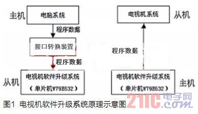
At present, the upgrade interface of the TV is generally a UART serial interface and an I2C interface, and the software upgrade system can be upgraded by using two interfaces. If the computer system does not have these two interfaces, it needs to be connected to the upgrade system through the interface conversion device.
System hardware implementation
The hardware block diagram of the portable TV software upgrade system is shown in Figure 2. The system mainly includes single-chip W79E632, FLASH memory, UART serial interface circuit, I2C interface circuit, interrupt circuit and status indicator.
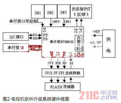
WINBOND company MCU W79E632 has 128k ISP (In-System Program) FLASH ROM, 4k LD (Loader program) FLASH ROM, software instructions are fully compatible with 51 MCU, high efficiency and fast speed.
W79E632 has UART serial interface, no I2C interface and SPI interface, I/O port P8, P9 analog I2C interface, I/O port P4~P7 analog SPI interface. FLASH storage uses NOR FLASH, 3.3V power supply. Since the FLASH is 3.3V power supply, the W79E632 I/O port level is 5V. To ensure data reliability, the system has a 5V/3.3V SPI bus conversion circuit.
The system's own boot program, initialization program, UART interface data read and write program, I2C interface data read and write program, SPI interface data read and write program are all placed in the internal ROM, FLASH memory is dedicated to store TV upgrade program data. The switches SW2 and SW3 generate low pulses to trigger the external interrupts INT0 and INT1 to control the reception and transmission of the I2C interface data; the serial interface interrupt controls the reception of the UART interface data, and the SW1 generates the low pulse to control the UART interface through the I/O port P3. The transmission of data. The upgrade system uses the W79E632 internal timer and I/O ports P2 and P1 to control the red/green indicator to indicate the current status. For example, the traffic lights are on, the upgrade system is running normally, ready to read and write; the red light is on, the green light is flashing, and the system is upgraded. Writing or reading FLASH memory.
System software implementation
The software implementation of the upgrade system consists of two parts: receiving and storing the TV upgrade program data sent by the computer system as a slave and the TV upgrade program data sent as a host to the television system for storage.
The system frequency is designed to be 22.1184MHz, the UART interface adopts 8-bit shift register mode, and the baud rate is 1/12 of the system main frequency. Each time a data byte is received or sent, an interrupt will be generated; the maximum transmission rate of the I2C interface is 100kb/s, the maximum transmission rate of the SPI interface is 2.2Mb/s.
The system self-test, initialization and other programs use 1000H as the starting address. After power-on, jump directly to 1000H, initialize the settings, set up the stack, set the UART interface, I2C interface and SPI interface related parameters; the red and green indicators are on, allowing interrupts. After that, the system runs normally, waits for the interrupt and monitors the status of the I/O port P3 to determine whether the system is operating as a master or a slave.
Receive and store upgrade program data as a slave
The upgrade system receives and stores the TV upgrade program data sent by the computer system as a slave. The process is shown in Figure 3.
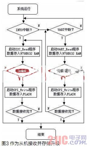
1. The system runs normally, open serial port interrupt, external interrupt and timer interrupt, waiting for interrupt.
2. When receiving the upgrade program data from the I2C interface, press the switch SW2 to generate the external interrupt INT0. All interrupts except the timer interrupt are masked, and the register and program pointer data related to the current state are temporarily stored on the stack. At the same time, the timer related parameters are set, so that the W79E632 can send a pulse signal with a period of 500ms to the I/O port P1 to control the green light to flash, indicating that data is being received. The serial port interrupt is automatically generated by the W79E632. If a serial port interrupt is generated, all interrupts except the serial port interrupt and timer interrupt are masked. The other settings are the same as the INT0 interrupt.
3. When the INT0 interrupt is generated, the I2C interface read program I2C_Read is started to write the data in the I/O port buffer register to the W79E632 internal RAM; if a serial interrupt is generated, the serial interface read program UART_Read is started, and the serial interface register is set. The data in the W79E632 is written into the internal RAM, and the serial port receives the interrupt flag RI to clear the next data.
4. The computer system sends 256 bytes as a data block, and sends an accumulated checksum to verify each time 256 bytes are sent. After the W79E632 verification data is valid, the FLASH write program SPI_Write is started, and 256 bytes of data in the RAM is written into the FLASH; after the writing, the response signal "RIGHT" is sent to the computer system, and the computer system continues to send data. W79E632 determines whether the next character is the "end" character (that is, the first character of each data block). If it is not the "end" character, it continues to receive data; if it is the "end" character, it starts the SPI_Write program and directly "ends" the character. Write to FLASH and then finish. If the W79E632 data is invalid after verification, the response signal "ERROR" is sent to the computer system immediately, and then ends.
5. At the end, W79E632 clears the data in internal RAM, I/O port buffer register and serial interface register, restores the timer, UART interface or I2C interface to the initial state, reads the data saved in the stack and writes the corresponding data. The register is restored to the state before the interrupt; the green light continues to flash for 2 seconds and then the interrupt is turned on, and the system resumes normal operation.
Send upgrade program data as a host
The process of upgrading the system as a host is shown in Figure 4.
1. The system runs normally, open serial port interrupt, external interrupt and timer interrupt, query the status of I/O port P3, wait for interrupt.
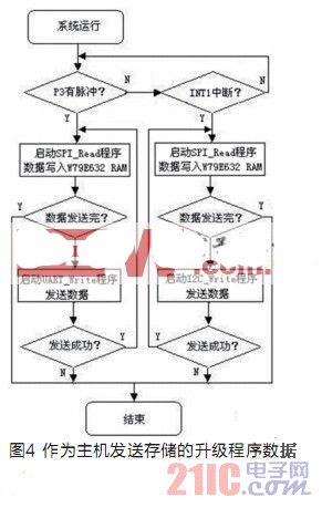
2. When the stored upgrade program data is sent from the I2C interface, press the switch SW3 to generate the external interrupt INT1. The setting at this time is the same as when INT0 is generated. If there is a pulse in the P3 port, all interrupts except the serial port interrupt and the timer interrupt are masked. The other settings are the same as the INT1 interrupt.
3. W79E632 starts the FLASH read program SPI_Read, reads the upgrade program data stored in the FLASH, and reads 256 bytes each time into the RAM of the W79E632. W79E632 determines whether it is an "end" character before storing the first character of the data block.
4.W79E632 reads the "end" character, indicating that the data is sent and the end processing is completed. Otherwise, the data is sent through the serial port or the I2C interface. If data is sent through the serial port, UART_Write is started to write the data in the RAM to the serial interface register for transmission; if the data is sent by the I2C interface, I2C_Write is started to write the data in the RAM to the I/O port buffer register for transmission. Each time 256 bytes of data are sent, the W79E632 continues to send an accumulated checksum and waits for a response from the TV. The "RIGHT" signal returned by the TV will continue to send data, and will end if the returned "ERROR" signal is received.
5. At the end, W79E632 clears the data in internal RAM, I/O buffer register and serial interface register, restores the timer, UART or I2C interface to the initial state, reads the data saved in the stack and writes the corresponding register. In order to restore the state before the interruption; the green light continues to flash for 2s and then interrupts, and the system resumes normal operation.
Conclusion
This paper proposes a portable TV software upgrade system based on the single-chip W79E632. The system can receive and store the TV upgrade program data through the UART interface or I2C interface, and can also store the upgrade program through the UART interface or I2C interface. The data is transmitted to the TV to implement software upgrades for the TV.
references:
[1] Preliminary W79E632 Data Sheet, Revision A1[D].Winbond Electronics Corp, 2004
[2] I2S bus specification[D]. Philips Semiconductors, 1986
[3] Zhuang Ziming, CHENG E. Software upgrade of terrestrial digital TV set-top box based on DMB-TH [J]. China Cable TV, 2008 (8): 809-813
[4] Liu Qingfeng. Software upgrade mechanism and attention of set-top box software [J]. China Cable TV, 2005 (12): 1134-1135
[5] Guo Jinghua, Ouyang Binlin. Realization of real-time simulation of SPI bus slave interface[J]. Journal of Northeast Agricultural University, 2007, 38(5): 669-671
[6] Lü Gang, Li Qiang. AVR MCU Software Analog UART Communication Interface[J].Microcontrollers & Embedded Systems,2003(1): 73-74
Led Parking Light: the sound, infrared or microwave-controlled LED lighting, by voice, infrared or microwave sensor signals into electrical signals to the surrounding environment, according to changes in the electrical signal to adjust the brightness of LED lamps state, to achieve on-demand lighting Effect.


LED Parking Light Usually are composed by the LED light source module, a detection module, LED power modules, network modules, and shell composition.
LED Parking Light Housing assembly (bottom shell, face mask and cover other accessories);
Detector assembly (pyroelectric infrared sensor, Fresnel lenses and secondary line);
Controller assembly (intelligent controller, drive module);

Mingxue Optoelectronics Co.,Ltd. has apply the I S O 9 0 0 1: 2 0 0 8 international quality management system certificate, For led parking light, we apply the CE, RoHS and SAA certificate for our led lighting product.
Our R & D team can handle highly customized designs and offer OEM and ODM services.
We hope to set up a long-term partnership with you through our high quality products and our Sincere Service!


LED Parking Light
Led Parking Light,Led Shoebox Light,High Power Parking Light,Waterproof Parking Light
Shenzhen Mingxue Optoelectronics CO.,Ltd , https://www.mingxueled.com