The main frequency range of the ECG signal is 0.05 "100Hz, the amplitude is about 0" 4mV, and the signal is very weak. The ECG signal is usually mixed with other biological signals, and the external electromagnetic field interference at the main frequency of 500 Hz makes the ECG noise background stronger and the measurement conditions more complicated, which brings certain difficulties to medical research, treatment and teaching. In this paper, through the analysis of the characteristics of the ECG signal, a simulation method of ECG signal based on MATLAB / SIMULINK is proposed. The rapid prototyping technology is used to convert the virtual simulation signal into the actual physical electrical signal through the input / output card, and the actual hardware circuit Connected together to form a semi-physical simulation model of ECG signals.
Fundamental
ECG
A typical ECG signal is shown in Figure 1, which is composed of P wave, Q wave, R wave, S wave and T wave. During the diagnosis process, the interval amplitude of these characteristic waves and the PR interval, ST interval and QT can be based on Judge the patient's condition at intervals.

Fourier series
If a function satisfies Dirichlet condition, it can be expanded into the form of Fourier series. The trigonometric function form of Fourier series is defined as follows:
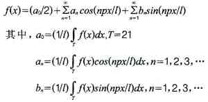
Dirichlet condition sufficient condition:
(1) The function is continuous in any finite interval, or there are only a limited number of discontinuity points of the first type (when t tends to this discontinuity point from left or right, the function has limited left and right limits);
(2) Within a period, the function has a finite maximum or minimum.
ECG signal simulation and result analysis
ECG signal simulation
This design plan is to treat the ECG signal as a combination of each triangle wave signal and sinusoidal signal, and then obtain each characteristic wave sequence through calculation, and then synthesize each wave into the final simulation signal. The specific implementation method is as follows:
(1) The QRS wave, Q wave and S wave of the ECG signal are realized by triangle wave.
(2) The P wave, T wave and U wave of the electrocardiogram signal are realized with a sine wave.
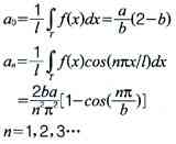
Triangle wave mathematical model establishment
The triangular wave mathematical model is established as follows:
For convenience of calculation, this function is expanded into the form of Fourier series:
In the formula,
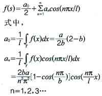
Sine wave mathematical model establishment
The sine wave model is as follows:
For convenience of calculation, this function is expanded into the form of Fourier series:
Analysis of simulation results
Through the above simulation scheme, the characteristic wave parameters of the simulated ECG signal are shown in Table 1, and the simulated waveform of the ECG signal is shown in FIG. 2.
Real-time ECG signal source design
The design scheme uses SIMULINK to realize the design of ECG signal generator. SIMULINK can easily carry out visual dynamic modeling, and the simulation process is interactive, you can modify the parameters at any time, you can immediately see the simulation results, and generate real-time signals that can be actually applied.
ECG signal generator implementation
In the design scheme, the ECG signal is regarded as a waveform composed of various characteristic waves. These characteristic waves include P wave, Q wave, QRS wave, S wave, T wave, and U wave. In the simulation design process, Q wave, QRS wave and S wave are realized by triangle wave, and P wave, T wave and U wave are realized by sine wave.
The design of the ECG signal generator is implemented with seven modules, of which the function of six modules is to realize the characteristic wave, and one module is used to synthesize each characteristic wave to realize the simulation of the ECG signal. The design results are shown in Figure 3.
As shown in Fig. 3, each ECG signal characteristic wave generating module has its own characteristic wave parameter input, and these parameters include amplitude, width and shift. In addition, the 6 ECG signal characteristic waveform generating modules have 2 common inputs, which are the length x of the ECG signal and the heartbeat period beat. Obviously, the SIMULINK model of the ECG signal generator can easily obtain the required ECG signal by changing the ECG signal parameters.
Real-time ECG signal generation
In the design scheme, the ECG signal generator designed by SIMULINK is used to generate a digital simulated ECG signal, which is led out by the D / A converter of Advantech's analog output data acquisition card PLC-812PG to generate real-time ECG signals. The principle block diagram is shown in Figure 4.
The MATLAB Embedded FuncTIon module only supports two-dimensional matrix operations, so attention should be paid to the conversion of two-dimensional data to one-dimensional data when outputting real-time ECG signals, that is, a two-dimensional matrix to one-dimensional matrix conversion module.
in conclusion
This solution solves the difficulties of complex hardware circuits, large noise, and difficulty in collecting individual ECG waveforms during the actual ECG signal acquisition process. It brings convenience to medical research and teaching, and has certain practical and reference value.
Electronic Components Resistor
Resistor (Resistor) commonly known as resistance directly in our daily life.It is a current limiting element. When the resistance is connected to the circuit, the resistance value of the resistor is fixed, usually two pins.Fixed resistors are those whose resistances cannot be changed.Resistance variable is called potentiometer or variable resistor.The ideal resistor is linear, that is, the instantaneous current through the resistor is proportional to the applied instantaneous voltage.Variable resistor for partial pressure.On the exposed resistor body, one or two movable metal contacts are pressed tightly.The contact position determines the resistance between any end of the resistance body and the contact.

Electronic Components Resistor,Metal Film Resistor,Metal Oxide Film Resistor
YANGZHOU POSITIONING TECH CO., LTD , https://www.yzpstcc.com