Introduction
Nowadays, as energy demand continues to rise, governments and power-saving agencies in various countries are increasingly concerned about power conversion energy efficiency and standby energy consumption. Since many devices are always powered on but do not perform specific functions, a variety of voluntary and mandatory standards have been introduced worldwide. These new standards focus on reducing the no-load standby energy consumption, and the minimum requirement is limited to 0.3W. Due to the increasing burden of energy consumption in this no-load mode, major TV manufacturers are seeking to further improve performance and limit standby energy consumption to less than 0.1W. Although this is not a mandatory performance requirement, it will help promote the popularity of ECO standby mode.
In addition to selecting the ECO standby mode, you can also use a completely off mode, this mode focuses on reducing energy consumption to below 25mW, or even reach 0W. If the most traditional solution is to use the total power switch, we will see another solution that is better in terms of cost and safety indicators later.
In the end, TV manufacturers will realize that green products can bring more market benefits. In the face of rising energy costs and environmentally conscious consumers, they highlight the difference between their products.
Overview
ECO standby power converter can provide extremely low energy consumption, and also supports full standby function, which can be turned on by remote control, infrared (IR) function and peripheral control (EU SCART specification). The current consumed by the converter in standby mode should be less than 8mA (or the energy consumption is less than 40mW), so as to ensure that the total energy consumption of the TV is less than 90mW. This may require the use of a dedicated standby microprocessor (µP), which has become a more advanced technology for ECO standby mode.
Traditional fixed frequency switching regulators have excellent performance in providing maximum output power, but they do not provide the best extremely low output power performance due to the use of cycle-hopping modes that use compressed current to mitigate possible noise problems. We used to like hysteresis mode switching regulators to reduce the number of switching cycles by lightly loading and limiting switching losses.
Even though the main power switch and cathode ray tube (CRT) TVs are widely used in Europe and Asia, single-panel TVs do not require components to comply with safety / standard specifications (voltage not higher than 4kV). Although not a mandatory requirement, we see more and more flat-panel TVs starting to be equipped with a main power switch to support the "green shutdown mode". Although this solution seems the simplest, in order to avoid breeding safety problems and fire risks (may require vanadium oxide (VO) enclosure plastic materials), high peak surge currents and the required isolation around the switch (switches and cables and The main isolation between the metal parts of the TV housing makes the mechanical design both complicated and expensive. The position of the switch in the chassis is also very important. Since the position of the cable may cause the EMI filter to become a "bypass" component, it may increase electromagnetic interference (EMI) problems.
Due to the excellent performance of the ECO standby solution under no-load conditions, we can provide a shutdown mode where the power consumption of the main power supply is less than 25mW. This shutdown mode is controlled by a small low-voltage / low-cost switch connected to the secondary side without adding any isolation and EMI problems. This scheme meets the most stringent safety requirements, does not allow the TV switch to be turned on (otherwise the switch is closed), and the energy consumption in any safety test is not higher than 15W.
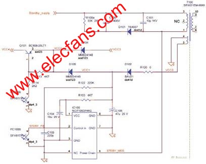
Figure 1 Primary side circuit diagram of standby switching power supply
To be able to maintain such low energy consumption in standby and off modes, we use relays to disconnect components that are not used in these modes. The relay is directly powered by a 5V standby power supply and is controlled by the TV microprocessor. In standby mode, it can avoid parasitic energy consumption of about 100mW (PFC peripheral components and main power filter X2 capacitor discharge impedance).
The standby switching power supply should be powered by a dedicated diode directly connected to the main power input (in front of the relay). Because the power in standby mode is limited, single-phase rectification is sufficient. The PFC output "take over" uses 400V to power the standby switching power supply. The 400V voltage is derived from the PFC in working mode. Provides up to 7.5W of power (1.5A current) at the 5V standby output.
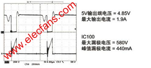
Figure 2 ON mode when 400V PFC output voltage and maximum output current are provided
Primary side of standby switching power supply
Because the start-up regulator is embedded, the standby switching regulator IC100 can start up within a short period of time within the main power supply voltage range (at 90Vac, the start-up time is less than 20ms). This IC operates in hysteresis mode, internally limits the maximum constant primary current, provides a voltage regulation function, and regulates the converted energy with a variable period. In order to improve the extremely low output energy consumption in standby mode, the controller uses extremely low frequency operation to maintain the same maximum current in each cycle, greatly reducing switching losses, thereby providing high energy efficiency for low energy consumption / ECO mode (at 90Vac Under voltage, the 71Hz skip-cycle mode frequency at no-load rises to 322Hz, thereby providing an output of 8mA / 40mW).
Secondary side of standby switching power supply
The power supply design provides a single 5V standby power supply with a maximum current of 1.5A in the on-mode. TLV431 (that is, shunt regulator IC101) is used for voltage regulation, reducing current consumption in ECO mode (because polarization requires lower current), and provides greater voltage margin for 5V power supply.
Functional close switch
The switch can be much smaller than the total power switch, requiring only 10V voltage and 2A DC current. The switch is connected to the secondary side, without any isolation from the metal parts of the TV set, and there is no risk of fire when the voltage is lower than 10V.
The whole scheme meets the safety requirements, and the TV is not allowed to switch to the on / operating mode when the switch is not in operation, and can ensure the energy consumption of the main power supply end in any safety test (short circuit or any electrical component open circuit) Less than 15W.
When there is no output load, the standby power supply will still work. When the 230Vac power supply is used, the energy consumption of the main power supply terminal is less than 25mW. This solution uses lower cost to achieve higher performance, and avoids possible safety issues, providing an excellent alternative to the main power switch.
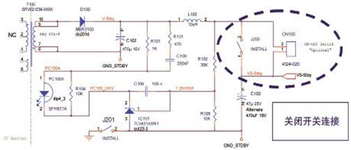
Figure 3 Secondary side circuit diagram of standby switching power supply
Standby / ON control and overvoltage protection (OVP)
The "standby" control derived from the TV's microprocessor will control the power supply, enabling the system to enter the on / working mode, or forcing it to be in standby mode. Since the "standby" controls voltages up to 5V, the signal transistor drive relay uses the main power supply voltage to power the PFC, while driving the optocoupler to supply all primary controllers / ICs with the standby power supply auxiliary voltage VCC1.
When the TV enters standby mode, both the relay and the optocoupler will be turned low by the standby control line and turned off.
The secondary 5V standby output is shorted to ground
In the case of an output short circuit to ground, the current in the IC will remain at the same peak value, but because the energy transfer cannot be completed, the system will work in continuous conduction mode, and the root mean square (RMS) current in the transformer, IC, and diode Much higher.
Since the regulator function is turned off, the controller driving the regulator pin has no feedback. Since there is no feedback control, the IC will stop working until the Vcc voltage drops low enough to restart. The power supply will work in a low-frequency (approximately 7kHz) boost or cycle skip mode, with 70% off time to avoid any over-temperature or safety issues.
Overall energy consumption and energy efficiency performance
• In off mode / no load, the input power is less than 25mW;
• At 5V standby, the input power is less than 90mW and the output power is 40mW;
• When the input voltage is 90Vac, the maximum current consumption of the standby terminal at 5V in standby mode is 500mA;
• When the input voltage is 230Vac, the maximum current consumption of the 5V standby terminal in standby mode is 1.5A;
• In conduction mode, when powered by 400Vdc from PFC, the current consumption is a maximum of 1.5A.
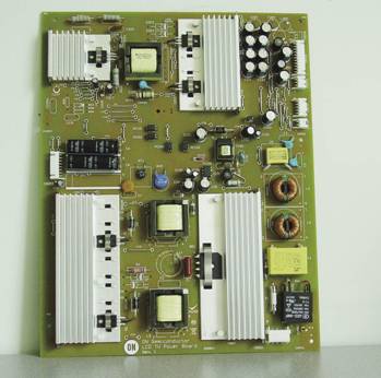
Figure 4 ECO standby power supply in GreenPoint reference design of ON Semiconductor's latest TV power supply
in conclusion
For TV applications, the ECO standby mode with energy consumption less than 90mW, full standby function, and compliance with all specifications can now be used. Although this mode requires a dedicated additional standby switching power supply, it does not require a complex design to have a high-power converter function and can provide high standby mode performance (additional switches that are critical to energy efficiency and safety). It is especially important that this solution has excellent "no-load" performance, which can further reduce energy consumption in an economical "off" mode, and also helps to improve reliability and avoid the safety associated with traditional high-voltage main power switch solutions. risk.
36W Wall Mounted Power Adapter
36W Wall-Mounted Power Adapter,12V3A Ac Power Supply Adapter,2V3A Power Adapter For Notbook,12V3A Power Adapter
Guangdong Mingxin Power Technologies Co.,Ltd. , https://www.mxpowersupply.com