[Introduction] Battery-powered products require an optimized LED driver circuit architecture that addresses many of the challenges of coexistence, such as space constraints, high energy efficiency, and battery voltage variations - either higher than the forward voltage of the LED, or low. There are two commonly used topologies, namely, a charge pump architecture/constant current source architecture in which LEDs are arranged in parallel, and an inductor boost architecture in which LEDs are arranged in series.
In the past few years, small color LCD displays have been integrated into a wider range of products. Color displays have been seen as a luxury configuration for mobile phones, but today, even in entry-level phones, color screens have become a standard. Fortunately, the economies of scale of the mobile phone industry (the global annual shipment of mobile phones is close to 1 billion units) reduce the cost of LCD color displays and integrate them into portable medical devices, universal entertainment remotes, digital photo frames/image viewing. Other products such as devices, educational toys, or the latest WiFi-enabled VoIP cordless phones are attractive.
The color LCD display requires a white backlight so that the user can view it normally in any lighting environment. The backlight subsystem includes a high-brightness white light-emitting diode (LED) array, a diffuser to diffuse light and a backlight driver to regulate the available power to a constant current to drive the LED. A 1 to 1.5 inch The display may contain 2 to 4 LEDs, while a 3.5-inch display may easily contain 6 to 10 LEDs. For LEDs, the light output is proportional to the current and because the LED has a very steep current - The voltage (IV) curve, where the current flowing through the LEDs is closely matched, is important to ensure a balanced backlight because the LEDs are typically distributed on one side of the LCD display. In addition, software controls are required to allow the user to adjust the brightness and compensate for the surrounding lighting environment. The color point of the LED may drift depending on the current flowing through the LED. Therefore, it is common to set the LED current to a fixed value and pulse width modulate the LED to reduce the average light output. There are a number of factors to consider when integrating a small color LCD display into a handheld product design and achieving the right balance of cost, performance and battery life.
Battery-powered products require an optimized LED driver circuit architecture that addresses many of the challenges of coexistence, such as space constraints, high energy efficiency, and battery voltage variations - either higher or lower than the forward voltage of the LED. There are two commonly used topologies, namely, a charge pump architecture/constant current source architecture in which LEDs are arranged in parallel, and an inductor boost architecture in which LEDs are arranged in series. Both solutions have compromises to consider. For example, the boost architecture ensures that all LEDs flow at the same current but require inductors for energy conversion. The charge pump architecture uses small capacitors for energy conversion, but all LEDs are connected in parallel. Arranged too tightly so that current matching becomes a thorny problem for balanced backlighting. Figure 1 shows an example of these two architectures.
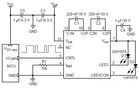
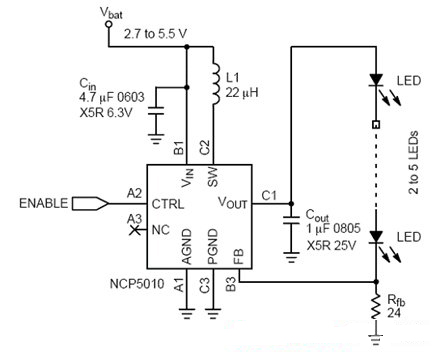
Figure 1: Circuit diagram of the charge pump and inductor LED driver.
The following points should be made during design
1. Evaluate the approximate usage time of the display
When selecting a white LED driver, you need to consider the frequency of use of the display. If the display is backlit for long periods of time, having a highly efficient converter is critical to battery life. Larger displays require more LEDs, while applications with longer display times benefit from a more energy-efficient boost topology. Conversely, if the display is only used for short-time backlighting, efficiency may not be a critical design parameter.
2. Carefully consider LED options
LED technology continues to improve rapidly, with manufacturers using new materials, manufacturing techniques and LED designs to deliver greater light output for the same amount of current, so that a display that requires four LEDs to backlight a few years ago is now It is possible to achieve the same backlight brightness with 2 LEDs. Not only that, the larger 4 to 7-inch displays that used to be backlit with cold cathode fluorescent lamps (CCFLs) are now turning to LEDs for backlighting. In addition, the forward voltage of the LED is tending to be lower. Therefore, it is necessary to consider not only the driver efficiency on the drive manufacturer's data sheet curve, but also the evaluation based on the selected LEDs. Table 1 lists some of the important specifications for several LEDs, showing the difference in forward voltage and luminance of these LEDs. It should be noted that the change in the forward voltage range is large, which means that the efficiency of the driver should be evaluated using the limits of the LED specification.
3. Pay attention to wiring
Even if each LED is driven with a very low current of 10 to 20 mA, the peak current flowing through the converter is significantly higher. This is true for inductive topologies because the peak switching current can be 10 to 20 times the average LED current. Therefore, it is necessary to use appropriate low-loss wiring technology. For charge pump type topologies, the capacitor should be placed adjacent to the driver to minimize loop area to avoid radiated switching noise. For an inductive boost converter, the input and output capacitors and the inductor are placed adjacent to the driver. In addition, the current setting resistor (Rfb) should be connected directly to the ground of the chip because errors between the internal reference and the sense voltage directly affect the LED current accuracy.
4. Test your test product in a real environment
Consider the performance of the display under high ambient light conditions and ensure that the software dimming control has sufficient dynamic range to adequately dim the display in the desired lighting environment.
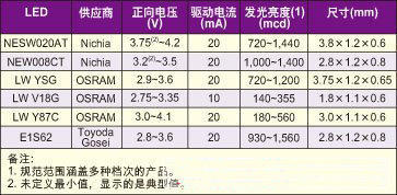
Table: Characteristic parameters of several different LEDs.
Should pay attention to avoid the following problems
1. Forgot to consider the boundary and failure mode
Errors always occur. If the LED is open or shorted to the ground, how should the driver handle this problem? For an inductive boost driver, if the LED string is open, the output will surge because the constant current charges the output capacitor, which requires overvoltage protection, but this feature may or may not be integrated into the driver. This can be a problem in factory testing because the display may not have been installed during certain test steps. In addition, it is important to assess the surge conditions when the product is turned on, as the large current draw here may reduce the battery voltage below the minimum operating threshold. This problem can be minimized by using soft start and/or software sequencing of different circuit modules.
2. Only stare at peak efficiency
Since the user can adjust the brightness of the backlight, it is important to consider the drive efficiency of the display backlight that is expected to be active during most of the working time. When evaluating the efficiency of a drive, you need to consider the expected operating conditions of the LED, the battery voltage range, and the forward voltage change. Inductive drivers have better peak efficiency and greater tolerance for input and output voltage variations.
3. Ignore external component selection
In all design cases, low equivalent series resistance (ESR) X5R or X7R ceramic capacitors should be considered to minimize losses. Also in the inductive case, the forward voltage drop of the Schottky rectifier and the ESR of the inductor can affect efficiency if there is an external one. For example, using an inductor with a 0.3Ω ESR to drive five LEDs in series at 20mA will be 5% more efficient than an inductor with 1.3Ω ESR. Of course, this is not without cost because of the ESR of the inductor. The lower the size, the larger the size corresponding to the same inductance value. Fortunately, there are many new small-sized inductors that allow LED drivers to be placed underneath the display.
Our latest USB Type-C socket offers optional splash protection (IPX4 level) and valuable circuit board design space.
Our latest USB Type-C socket protects equipment in harsh environments. It has the industry-leading IPX8 waterproof performance and meets the IEC60529 standard.
5P Through Hole Type,USB Through Hole Type,MICRO USB Straddle B Type
ShenZhen Antenk Electronics Co,Ltd , https://www.antenk.com