The CAN bus design specification has strict regulations on the parameters of the signal edge of the CAN node. If it does not meet the specifications, it will be prone to abnormal working state after the network is set up on site, and communication failure occurs between the nodes. The specific requirements are shown in Table 1, which is the test standard "GMW3122 Signal Edge Standard".
Table 1 GMW3122 Signal Edge Standard
| Test parameters | Recessive->dominant edge | Dominant->recessive edge | condition | ||
| Minimum value | Typical value | Minimum value | Maximum | ||
| High speed CAN (minimum load) 500K~1Mbps | 15ns | 150ns | 15ns | 300ns | Typical value is 500Kbps, C1=100pF, C1=100pF, C3=0pF |
| High speed CAN (maximum load) 500K~1Mbps | 15ns | 1300ns | 15ns | 1300ns | Typical value is 500Kbps, C1=4700pF, C1=4700pF, C3=3300pF |
| Medium speed CAN (minimum load) 100K~250Kbps | 15ns | 600ns | 15ns | 1200ns | Typical value is 125Kbps, C1=100pF, C1=100pF, C3=0pF |
| Medium speed CAN (maximum load) 100K~250Kbps | 15ns | 2650ns | 15ns | 2650ns | Typical value is 125Kbps, C1=10000pF, C1=10000pF, C3=6800pF |
Therefore, each manufacturer must test the signal edge parameters of the CAN node DUT (device under test) before the product is put into use. Generally, the CAN test method using the GMW3122 signal edge test is described as follows:
As shown in Figure 1, we define 20% ~ 80% of the signal transition process as the rise and fall times of the signal.
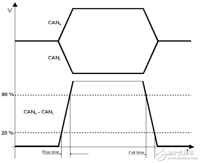
Figure 1 rising edge and falling edge
Under the condition of capacitor matching shown in Table 1, select the adaptation conditions of the DUT under test, as shown in Figure 1, the test wiring is less than 1 m, test the rise time and decrease of the signal differential level of the measured DUT Vdiff=VCANH-VCANL Time (voltage range of 20% to 80%).
Rise time: The transition time from recessive to dominant. Fall time: The transition time from dominant to recessive. When measuring, each edge is measured at least 1000 times to determine the minimum and maximum values ​​of the edge rise/fall time.
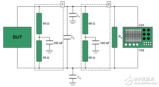
Figure 2 Signal edge measurement wiring diagram
It can be seen that although the method can measure the rising edge and the falling edge of the CAN node, it needs to use the oscilloscope to perform thousands of manual operation measurements, that is, waste time manpower, and there may be measurement error, and due to the limited number of samples, It does not necessarily reflect the true performance of the device. Therefore, in order to simplify the operation, improve the accuracy of measurement results, and save labor costs, Guangzhou Zhiyuan Electronics Co., Ltd. improved the test method, using CANScope-Pro bus analyzer, CANScope-StressZ expansion board for automatic large-volume statistical analysis and measurement. .
The test plan is as follows:
1. Test using CANScope-Pro and CANScope-StressZ expansion board, after the DUT is powered on, it will always send CAN messages. CANScope does not check the bus response, its black test pen (ground) is to be shared with the DUT's CAN transceiver. As shown in Figure 3, a test connection is made.
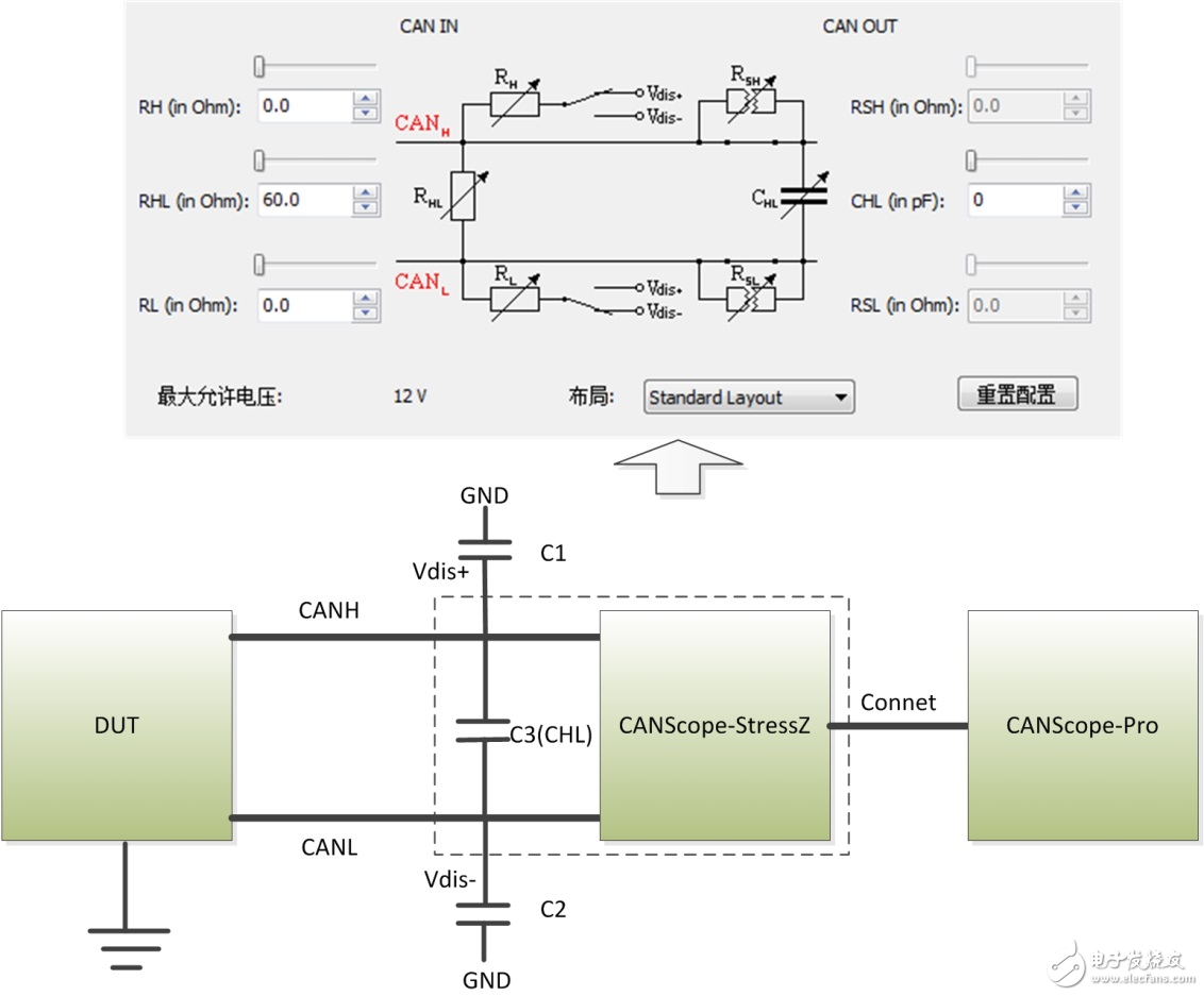
Figure 3 Edge test wiring diagram
2. As shown in Figure 4, the interference source is configured externally to facilitate the external input interfaces of Vdis+ and Vdis-. Note that GND is the interface between the Vdis+ and Vdis- external inputs for ground connection to the CAN transceiver.
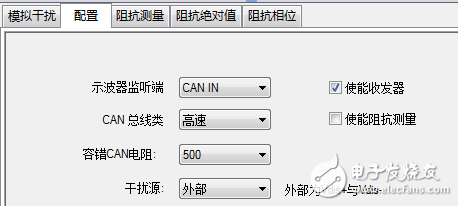
Figure 4 Adjusting the CANScope-StessZ interference source to external
3. Select the corresponding test conditions for testing as shown in Table 1.
Connect Vdis+ and GND, Vdis- and GND to the C1 and C2 capacitors required by Table 1. Adjust the control panel of CANScope-StressZ to adjust CHL to the C3 capacitor required in Table 1. Then start CANScope-StressZ.
4. Start the DUT, send the message, record the message and waveform for a period of time through CANScope, click the stop of CANScope, and click the edge statistics in the toolbar. As shown in Figure 5
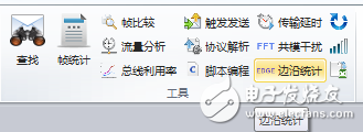
Figure 5 Edge Statistics icon
5. Click on Edge Statistics to get the results, as shown in Figure 6.
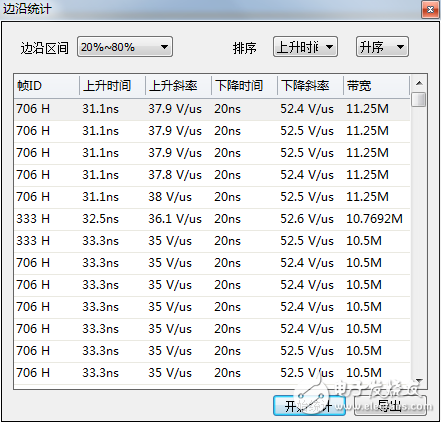
Figure 6 Edge statistics (ascending order)
6. Click Sort as rise time, in ascending order, the first is the rise time minimum, as shown in Figure 6, which is 31.1 ns; in descending order, the first is the rise time maximum, as shown in Figure 7. Similarly, the minimum and maximum values ​​of the fall time can be analyzed.
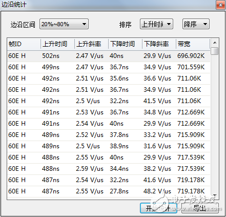
Figure 7 Edge statistics (in descending order)
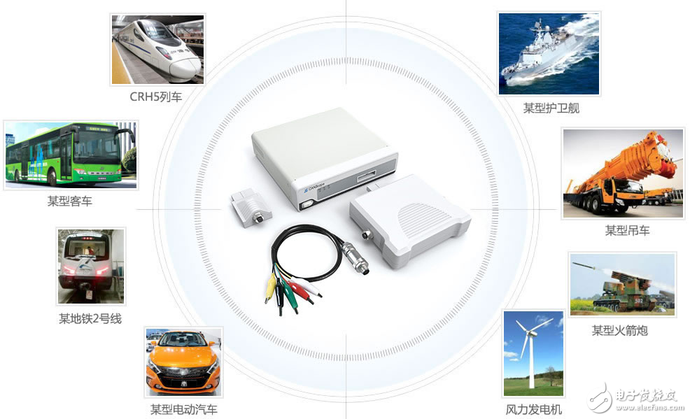
CANScope analyzer is a comprehensive CAN bus development and testing tool developed by Zhou Ligong Zhiyuan Electronics. It integrates mass storage oscilloscope, network analyzer, bit error rate analyzer, protocol analyzer and reliability test tool. Integrate and correlate various instruments organically; redefine the development and test methods of CAN bus, and evaluate the correctness, reliability and rationality of CAN network communication in multiple angles; help users quickly locate faulty nodes and solve CAN bus The various problems of the application are the ultimate tools for CAN bus development testing.
Here you can find the related products in LED Magnetic Light, we are professional manufacturer of Folding Spot Lighting, Led Magnetic Light, 24W Spot Lighting , Folding Light 12W. We focused on international export product development, production and sales. We have improved quality control processes of LED Magnetic Light to ensure each export qualified product.
If you want to know more about the products in LED Magnetic Light, please click the product details to view parameters, models, pictures, prices and other information about Folding Spot Lighting, Led Magnetic Light, 24W Spot Lighting, Folding Light 12W.
Whatever you are a group or individual, we will do our best to provide you with accurate and comprehensive message about LED Magnetic Light!

LED Magnetic Light
Folding Spot Lighting,Led Magnetic Light,24W Spot Lighting,Folding Light 12W
Guangdong Decosun Lighting Technology Co.,Ltd , https://www.decosun-lighting.com