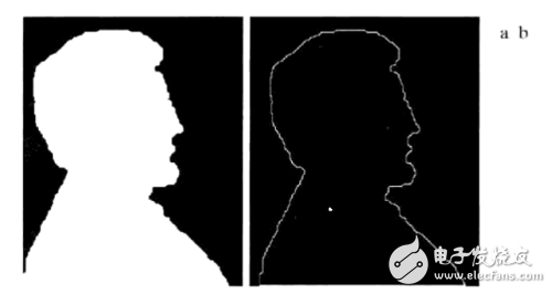
Figure 1: Binary image boundary extraction demonstration
As shown in Fig. 1, Fig. 1a represents a simple binary image. After applying the boundary extraction algorithm, the result is an image as displayed in Fig. 1b, which highlights the outline of the white region. This process helps in identifying the edges that define the shape of objects within the image.
2. Boundary Extraction AlgorithmIn this method, black pixels are considered as the background, with '1' representing white and '0' representing black. The algorithm uses a 3x3 template to determine the boundaries. If all nine pixels in the window are '1', the output is '1'. Conversely, if all are '0', the output is also '1'. Otherwise, it outputs '0'. This approach ensures that only the edges are highlighted while preserving the internal structure of the object.
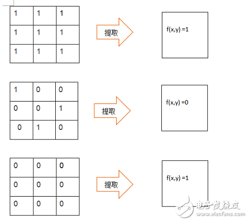
Figure 2: Binary image boundary extraction demonstration
3. FPGA Binary Image Boundary Extraction Algorithm Implementation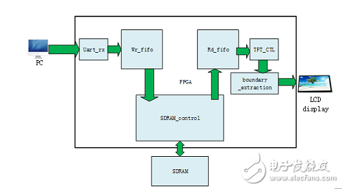
Figure 3: FPGA module architecture for binary image expansion
In the design, a serial port is used to input the binary image data into the FPGA. The following Verilog code implements the boundary extraction logic:
`timescale 1ns/1ps
module boundary_extraction(
input clk, // pixel clock
input rst_n,
input hs_in,
input vs_in,
input [15:0] data_in,
input data_in_en,
output hs_out,
output vs_out,
output reg [15:0] data_out,
output data_out_en
);
wire [15:0] line0;
wire [15:0] line1;
wire [15:0] line2;
reg [15:0] line0_data0;
reg [15:0] line0_data1;
reg [15:0] line0_data2;
reg [15:0] line1_data0;
reg [15:0] line1_data1;
reg [15:0] line1_data2;
reg [15:0] line2_data0;
reg [15:0] line2_data1;
reg [15:0] line2_data2;
reg data_out_en0;
reg data_out_en1;
reg data_out_en2;
reg hs_r0;
reg hs_r1;
reg hs_r2;
reg vs_r0;
reg vs_r1;
reg vs_r2;
wire [18:0] result_data;
Line3x3 line3x3_inst(
.clken(data_in_en),
.clock(clk),
.shiftin(data_in),
.shiftout(),
.taps0x(line0),
.taps1x(line1),
.taps2x(line2)
);
always @(posedge clk or negedge rst_n) begin
if (!rst_n) begin
line0_data0 <= 16'b0;
line0_data1 <= 16'b0;
line0_data2 <= 16'b0;
line1_data0 <= 16'b0;
line1_data1 <= 16'b0;
line1_data2 <= 16'b0;
line2_data0 <= 16'b0;
line2_data1 <= 16'b0;
line2_data2 <= 16'b0;
data_out_en0 <= 1'b0;
data_out_en1 <= 1'b0;
data_out_en2 <= 1'b0;
hs_r0 <= 1'b0;
hs_r1 <= 1'b0;
hs_r2 <= 1'b0;
vs_r0 <= 1'b0;
vs_r1 <= 1'b0;
vs_r2 <= 1'b0;
end else if (data_in_en) begin
line0_data0 <= line0;
line0_data1 <= line0_data0;
line0_data2 <= line0_data1;
line1_data0 <= line1;
line1_data1 <= line1_data0;
line1_data2 <= line1_data1;
line2_data0 <= line2;
line2_data1 <= line2_data0;
line2_data2 <= line2_data1;
data_out_en0 <= data_in_en;
data_out_en1 <= data_out_en0;
data_out_en2 <= data_out_en1;
hs_r0 <= hs_in;
hs_r1 <= hs_r0;
hs_r2 <= hs_r1;
vs_r0 <= vs_in;
vs_r1 <= vs_r0;
vs_r2 <= vs_r1;
end
end
always @(posedge clk or negedge rst_n) begin
if (!rst_n) data_out <= 16'h0000;
else if (data_out_en1) begin
if ((line0_data0 == 16'h0000) && (line0_data1 == 16'h0000) && (line0_data2 == 16'h0000) &&
(line1_data0 == 16'h0000) && (line1_data1 == 16'h0000) && (line1_data2 == 16'h0000) &&
(line2_data0 == 16'h0000) && (line2_data1 == 16'h0000) && (line2_data2 == 16'h0000))
data_out <= 16'hffff;
else if ((line0_data0 == 16'hffff) && (line0_data1 == 16'hffff) && (line0_data2 == 16'hffff) &&
(line1_data0 == 16'hffff) && (line1_data1 == 16'hffff) && (line1_data2 == 16'hffff) &&
(line2_data0 == 16'hffff) && (line2_data1 == 16'hffff) && (line2_data2 == 16'hffff))
data_out <= 16'hffff;
else
data_out <= 16'h0000;
end
end
endmodule
4. Experimental Results
Figure 5: Experimental original picture 1

Figure 6: Experimental original picture 2
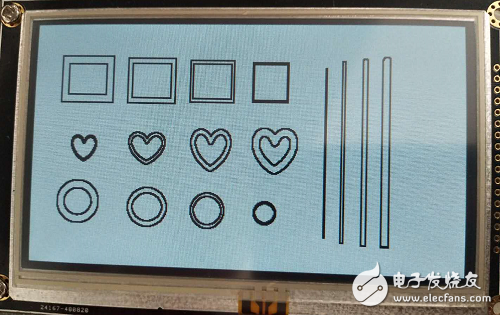
Figure 7: Experimental results – Figure 1
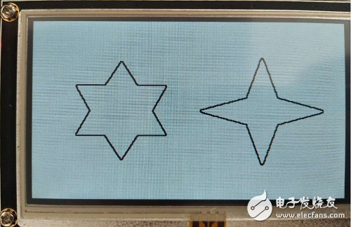
Figure 8: Experimental results – Figure 2
Analysis of the results: When comparing Figure 5 and Figure 7, thicker lines appear on the edges, while the thinnest line is not extracted because it contains only three pixels. The edges are black, and since black areas are connected, the lines look thicker. In contrast, Figures 6 and 8 show accurate edge detection without any issues. This confirms the effectiveness of the algorithm in extracting boundaries from binary images using an FPGA-based implementation.
Solar Mounting System,Solar Water Panel Stand,solar panel metal ground mount,ground mounted solar
Hebei Jinbiao Construction Materials Tech Corp., Ltd. , https://www.pvcarportsystem.com