1 Introduction
The AnTI-lock Braking System (ABS) can effectively prevent the vehicle from locking up during the braking process, thus avoiding the dangers of steering failure and tail-fail caused by wheel lock and ensuring the vehicle. Safe braking. Among them, the controller (ie, electronic control unit, ECU) is the control core of the entire ABS, and is also the main key in the development process of ABS. The traditional ABS development process requires a large number of vehicle road tests to verify the ABS control software functions, subject to human and physical constraints, making the ABS development cycle quite long.
Based on Infineon's XC164CS and Analog Devices' AD5336 chip, this paper designs a simple ABS controller development device that can test most of the functions of ABS control software without the need for a complete vehicle or even without the need for a brake. The development provides great convenience.
2 system composition
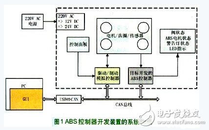
As shown in Figure 1, the designed ABS controller development device mainly includes three parts: one is the drive/brake analog controller, which is mainly used to simulate the driving and braking of the wheel, and the other is the hardware device part, including four representatives. The ring gear of the wheel and four motors that drive four ring gears respectively, four speed sensors, a control panel for various controls, and LED indicators for indicating the status of each solenoid valve, ABS motor and warning light Third, the GUI interface software running on the PC of the host computer is mainly used for various parameter settings, as well as collecting and monitoring various states of the ABS controller in real-time operation, including the original wheel speed, the reference vehicle speed, and the status of each solenoid valve. Wait.
3 drive / brake analog controller design
The main core of the ABS controller development device of this design is the design of the drive/brake analog controller. The functions that must be implemented include:
(1) The ring gear can be stably operated at a certain speed according to the setting;
(2) The gear ring can be quickly adjusted with different acceleration and deceleration to simulate the wheel speed change when the vehicle brakes under different road conditions and different working conditions, and the precision of the speed regulation is high;
(3) Real-time communication with the ABS controller developed by the target and the GUI software of the host computer.
According to the functional requirements, the circuit block diagram of the designed drive/brake analog controller is shown in Figure 2.
The main control chip is the Infineon 16-bit single-chip XC164CS, the main advantages are as follows:
(1) The operation speed is fast, the execution speed of the instruction is single clock cycle, and the maximum allowed clock frequency is 40M Hz;
(2) The memory capacity is large, and there is a 128KB rewritable flash for storing code and a SRAM for storing 2KB dual port RAM + 2KB data for data variables;
(3) Rich internal resources. Interrupt system with 16 & TImes; 8 priority levels, up to 80 interrupt sources, 2 groups of 5 16-bit timer/counter units, 14 10-bit precision A/D conversion channels, 2 groups of 32 capture/compare Channel, 2 asynchronous/synchronous serial interfaces (ASC), 2 high-speed synchronous serial interfaces (SSC), 2 CAN interfaces and up to 79 normal I/O lines;
(4) Program downloading and debugging is convenient. It has an on-chip bootstrapping program. It can download programs through the serial port, with on-chip debugging interface (OCDS), and can perform single-step and breakpoint debugging on the program through Keil-C166 and other compilers.
These advantages of the XC164CS fully meet the requirements of high-speed real-time control of this design.
Since the XC164CS requires two core voltages of 5V and 2.5V for proper operation, the TLE7469GV52, which can generate these two voltages, can be used as a power management chip to simplify the circuit design. The TLE7469GV52 is an Infineon LDO power chip with low Voltage alarms, overheating and overload protection, and watchdog functions provide an excellent power management solution for this design.
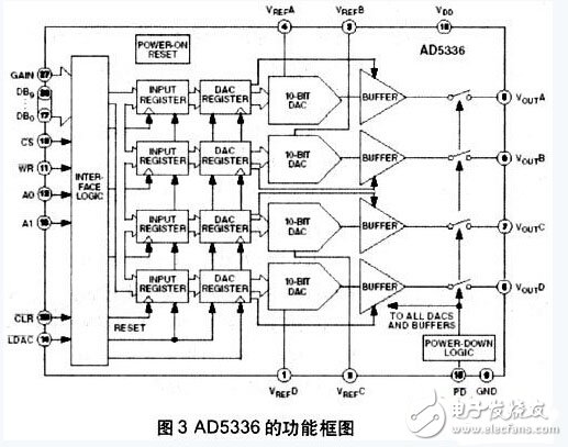
For motor control, this design uses a voltage-regulated DC motor, using AD5336 from Analog Devices as the D/A output chip for driving the motor. Figure 3 is a functional block diagram of the AD5336. The chip features four on-chip features. A separately controlled 10-bit precision D/A output channel, low power consumption, parallel interface, D/A conversion update time only 6μs, can fully meet the requirements of high precision and fast speed regulation of the motor in this design, Each D/A channel on the chip has a rail-rail output buffer amplifier with strong load capacity, so it can directly drive the voltage-regulated DC motor without any peripheral circuit. This way, the motor drive circuit can be greatly simplified. It also simplifies the design of the motor control program.
In this design, the passive magnetoelectric wheel speed sensor is adopted, and its output is a sinusoidal signal. In the wheel speed processing module, LM139 is used as a voltage comparison chip to realize the conversion of the sinusoidal signal to the square wave signal, and the CC2 of the XC164CS is utilized. The module captures the wheel speed pulse and monitors the rotation speed of the four ring gears in real time to realize the feedback control of the rotation speed of the ring gear motor, thus ensuring the accuracy of the ring gear speed control. The CAN interface is designed to meet the communication between the drive/brake analog controller, the target ABS controller and the host computer GUI software. The OCDS interface and ASC interface are designed for easy program download and debugging.

4 software design
The core principle of this development device is to simulate the brake with the drive/brake analog controller, and transform the ABS controller developed by the target to the brake, that is, to control the pressure, decompression, pressure holding, etc. by controlling each solenoid valve. To send the corresponding control information to the drive/brake analog controller. The drive/brake analog controller obtains the speed regulation of the ring gear motor and the speed sensor of the ABS controller through the ring gear according to the control information sent by the ABS controller, simulating the pressurization, decompression, and pressure holding of the brake. The wheel speed signal, in turn, continues the ABS brake control to achieve the purpose of detecting the ABS brake control software.
In addition, the influence of different road surfaces is also considered in the software design, that is, when braking on the road surface with different adhesion coefficient, the driving/braking simulation controller reflects the change in the rotation speed of the ring gear motor by simulating the action of the brake. In this design, the drive/brake simulation controller can simulate the braking on four road surfaces with high adhesion road surface, low adhesion road surface, abrupt adhesion coefficient road surface (ie, facing road surface) and adhesion coefficient separation road surface (ie, butt road surface). Happening.
According to the above software design, the following describes the working process of the development device and the verification of the ABS controller.
(1) Connect the target ABS controller to the system and power it on. The drive/brake analog controller analyzes the data packets on the CAN bus in real time. When receiving the speed setting and adjustment commands of the GUI software, The drive/brake analog controller rotates the ring gear motor at a certain speed according to the corresponding setting. The ABS controller should calculate various parameters such as wheel speed, wheel acceleration and deceleration in real time, and send it to the CAN bus. on. The GUI interface prints the information onto the screen in a graphical manner, etc., so that the various calculations of the ABS controller can be observed in real time.
(2) Select a road surface through the GUI interface and issue a brake command. The drive/brake simulation controller first simulates the normal brake and brakes the ring gear motor at a fixed deceleration. At this time, the ABS controller The detection of the ring gear speed sensor signal should be carried out to determine the need to enter the ABS brake intervention, so as to send corresponding control information to the CAN bus, the drive/brake motor simulates the brake action according to the control information to adjust the ring gear motor. Through the change of the rotational speed of the ring gear and the observation of the LED indicator, and the various calculation results of the ABS controller obtained on the GUI interface, including the wheel speed curve and the state of the solenoid valve, it can be verified whether the control flow of the ABS controller is correct.
5 Conclusion
Based on the high-performance 16-bit single-chip XC164CS and the high-precision D/A converter chip AD5336, this paper successfully designed and developed a drive/brake analog controller that can simulate the wheel speed change during vehicle braking, using the motor to drive the ring gear. The way to simulate the wheel operation, using a simple LED indicator to indicate various solenoid valve status and ABS motor status, can verify most of the control functions of the target ABS controller, for the newly developed ABS controller, only need to control it The software adapts to the right amount of modification of the operation of the development device without the participation of the whole vehicle or the brake, and does not need to carry out a large number of road experiments, thereby greatly reducing the development cost of the ABS and greatly shortening the ABS development cycle.
ACCURATE and RELIABLE: This oximeter can measure and monitor heart rate, SpO2 and pulse intensity with high accuracy. Displays waveform (plethysmograph) and digital readings, as well as pulse bar graphs, to visually indicate any irregularities or abnormalities, such as weak heartbeat.
EASY TO USE: Insert finger into rubber of the pulse oximeter and press "on". Intelligent tool for patients, exercise recovery, elderly, hikers, climbers (monitor the oxygenation rate of cells, for overall health). Essential to take reading without moving the body or hand to obtain accurate result.
LIGHT AND PORTABLE: Monitor is very light, small in size, low in power consumption and easy to carry with detachable lanyard; so, you can measure oxygen saturation anywhere. Auto power off s seconds after removing finger saves battery life
Medical Diagnostic Pulse Oximeter
Pulse Oximeter Sensor,Best Pulse Oximeter,Medical Diagnostic Pulse Oximeter,Blood Oxygen Saturation Monitor
Axiswell Technology Co., Ltd , https://www.medhealthycare.com