For portable devices such as smartphones or tablets, the battery is not a very reliable power source. In addition to the limited effects of variable capacity, temperature and aging, the internal resistance is an uncertain and often changing parameter. In the power management system, the proper use of the bypass mode will effectively address the challenges of internal resistance changes.
For portable devices such as smartphones or tablets, the battery seems to be a good stable power source. Simply add a buck-boost regulator and the power supply problem is almost completely solved. If you can effectively control the charge/discharge cycle and have a good battery detection subsystem, you should be able to get the required voltage and current.
However, in fact the battery is not a very reliable power source. In addition to the limited effects of variable capacity, temperature and aging, the main disadvantage is that the internal resistance (combined protection switch impedance and battery characteristics) can vary from tens of mΩ to hundreds of mΩ. More complicated is that the internal resistance also has a frequency dependence.
In a typical application, both ends of the battery (usually 2.5V∼4.35V, depending on the chemical) are connected to the input of the system power management unit, and the system power management unit establishes the system power rail for the different subsystems. Some standard circuits in smart phones, such as high-performance application processors/CPUs, high-current USB OTGs, camera flashes, or enhanced audio, have caused a wide variation in battery voltage.
This article describes a new power supply design that combines a boost regulator with an integrated low-impedance bypass switch. In addition to providing a wider operating voltage range, it also automatically boosts the output to below the set target. The output voltage. In addition, it can use the external control pin to call the bypass mode, which can reduce the quiescent current to a few microamps.
Internal resistance has a significant impact on battery lifeMost mobile devices today have multi-core CPUs and high-power graphics processing units (GPUs), as well as audio amplifiers and large displays, which are often the most power-hungry components in mobile devices. When the system performs resource-intensive tasks, the current drawn by the power management system from the battery often increases by two or three amps instantaneously due to a sudden increase in load. As a result, the battery voltage drops periodically, and some of the output of the system power management unit loses regulation. In the worst case, the system management unit triggers the cutoff voltage too early, causing a power outage.
Figure 1 shows the power-down of three batteries with the same capacity but different internal resistance values. When a high current pulse load occurs, the battery with a higher internal resistance has a shorter battery life.
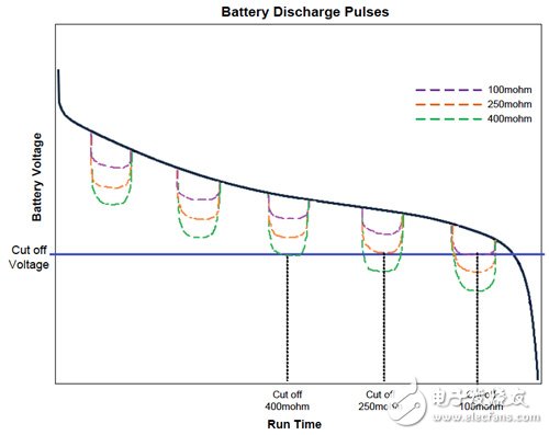
Fig.1 Discharge curve of different internal resistance in pulsed load scenario
Bypass mode provides higher operating voltage transient response performance can not be ignoredIn order to overcome the above challenges of mobile device power management and provide new operational advantages, a boost regulator that supports Bypass Mode is a solution. Take On Semiconductor's FAN48623 boost regulator as an example. When operating, when the input voltage VIN exceeds the target output voltage VOUT, the FAN48623 automatically switches to bypass mode, as shown in Figure 2. In bypass mode, the battery is connected directly to the output with very low impedance.
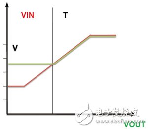
Figure 2 automatic bypass mode
In addition to automatic bypass conversion, designers can force the unit into bypass mode at any time. In forced bypass mode, only 2 to 3μA of quiescent current is available, but there is still enough battery voltage available for wake-up operation. Figure 3 shows the transition between the boost mode controlled by the nBYP signal and the low IQ forced bypass mode.
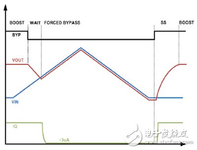
Figure 3 Low IQ forced bypass
Forcing the FAN48623 into bypass mode allows full battery output and near zero consumption, providing maximum supply voltage with minimal loss. The true load disconnect function also means that the "leakage load" can be disconnected from the battery voltage.
Compare the boost that supports bypassing with the traditional way of using a buck/boost regulator. In the traditional way, boost conversion limits overall efficiency when VIN is low. Higher efficiency (up to 96%) is achieved with a bypass topology with a bypass, and overall end-to-end efficiency remains high even when the regulator is placed in series with other buck regulators or LDOs. With boost plus bypass, the boost conversion efficiency is 10% higher than the equivalent buck-boost solution ("1A load current range").
When sudden load changes occur, the battery and power subsystem are stressed. When the load increases and the battery and power supply cannot cope, the power system will face even more difficult challenges. Assuming a battery internal resistance of 200 mΩ, when a 1 A load is applied, the battery voltage rapidly drops from the initial charging voltage of 4.2 V to less than 4 V due to the ESR reduction.
Now let's take a look at the system dynamics using the FAN48623 boost plus bypass method. Due to the fast boost mode conversion, the control loop can handle higher VIN (dV/dt) slew rate, as shown in Figure 4, where the 600mV line voltage instantaneously changes from 3.0 to 3.6VIN, the falling edge is 10μs, and the load current is 500mA. The output voltage VOUT is 3.3V.
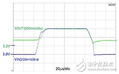
Figure 4 Line transient response in automatic bypass mode
The transition between boost and bypass modes of operation is fast: when VIN is greater than the target VOUT and follows the transient very closely, the IC enters bypass mode within 5μs.
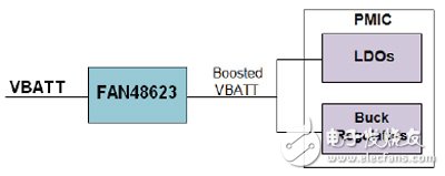
Figure 5 Schematic diagram of the application of the PMIC internal boost regulator 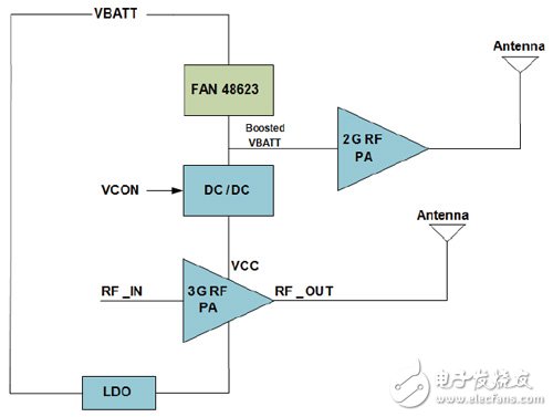
Figure 6 Application of boost RF DC/DC
led keychain,Key chain with led light,LED Key Chain,Led promotional key chain,
LED Key Chain,PVC Key Chain With LED,Key Chain With LED Light,LED Promotional Key Chain
AST Industry Co.,LTD , https://www.astsoundchip.com