RF filters are critical in wireless communication systems, functioning as frequency bands and channels, and filtering out harmonics to suppress spurs. In fact, for most modern filter designs, RF/microwave simulation software is an absolutely necessary tool for evaluating filter performance. Advanced Design System-ADS, a large EDA software launched by Agilent, is one of the best in the world. It is also one of the most used software for microwave circuit and communication system simulation in universities and research institutes in China. Based on the theoretical design, this paper uses ADS software to optimize the design of the coupled microstrip linepass filter, which saves the design time and improves the accuracy of the scheme design and the efficiency of the scheme design.
1, bandpass filter design - theoretical design 1.1 bandpass filter design - design indicatorsThe design specifications for the coupled microstrip linepass filter are as follows:
(1) Passband frequency range: 902~928 MHz, center frequency is 915 MHz;
(2) The in-band ripple is less than 3 dB;
(3) Stopband loss: attenuation below 850 MHz and above 950 MHz is greater than 40 dB;
(4) In-band input/output port reflection coefficient is less than -20 dB.
The design of the coupled microstrip linepass filter uses FR-4 as the substrate material. The substrate parameters are: d=1.6 mm, Er=4.5, tan δ=0.02, and the thickness of the copper conductor is t=0.035 mm.
1.2 Bandpass Filter Design - Theoretical CalculationWhen the frequency reaches or approaches GHz, the filter is usually composed of distributed parameter elements, which can form not only a low-pass filter but also a band-pass and band-stop filter. The parallel coupled microstrip transmission line consists of two unshielded parallel microstrip transmission lines that are close together. Due to the interaction of the electromagnetic fields between the two transmission lines, there is power coupling between the two transmission lines. This transmission line is therefore called Coupling the transmission line. The parallel coupled microstrip line can form a bandpass filter. This filter is composed of 14 wavelength coupling segments and is a commonly used distributed parameter bandpass filter. When two unshielded transmission lines are close together, there is power coupling between the transmission lines due to the interaction of the electromagnetic fields between the transmission lines. This transmission line is called a coupled transmission line. According to the transmission line theory, each individual microstrip line is equivalent to a small series inductor and a small parallel capacitor. The characteristic impedance of each microstrip line is Z0, the length of the mutual coupling part is L, the width of the microstrip line is W, the distance between the microstrip lines is S, the even mode impedance is Ze, and the odd model impedance is Z0. Although a single microstrip line unit has filtering characteristics, it does not provide a steep pass-to-stop band transition. If multiple units are cascaded, the cascaded network can have good filtering characteristics. The filter design first selects the appropriate low-pass filter prototype, and the order of the filter can be determined based on the attenuation of the 950 MHz frequency point greater than 40 dB. The frequency conversion formula using the bandpass filter is as follows:
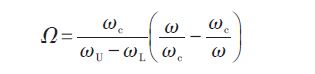
To obtain 40 dB of attenuation at the corresponding normalized frequency point Ω = 2.64 of the low-pass filter prototype, the order of the filter is at least N = 4, then a 5-band coupled microstrip line cascade is required. According to the required attenuation and ripple in the design index, the Chebyshev design method is selected, and the component parameters of the 4th-order Chebyshev filter with 3 dB ripple are g0=1, g1=3.438 9, g2=0.748 3 ,g3=4.347 1,g4=0.592 0,g5=5.809 5.
The odd-mode and even-mode of the transmission line in the coupled microstrip line-pass filter generate coupling effects through the common ground plate, and result in odd-mode impedance and even mode-resistance. The formulas are as follows:
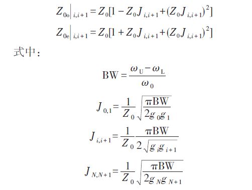
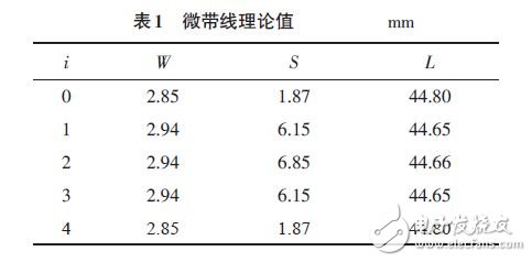
For the parallel coupled microstrip line, the linear calculation between the physical size and the electrical parameter can be performed by using the tool LineCalc in the ADS software, and the parallel coupling is calculated according to the calculated characteristic impedance of the parallel coupled microstrip line odd and even modes. The angle and separation distance of the microstrip line conductor strip. From the above characteristic impedance, the actual size of the microstrip line is shown in Table 1.
14gram tealight candles can burning 4-4.5hours .and it is made of paraffin wax .100% paraffin wax .
and burning is very goods ,no smoke and no smell
packing have 100pcs/bag and 50bag/ctn ,polybag or box .with client design or my factory design .
price same quality better
quality same price better .
pls be free to contact with me ,Angel 008615081129555
14 Gram Tealight Candle,Slow Burning Tealight Candle,Tealight Candles For Church,Custom Packaging Tealight Candle
Shijiazhuang Zhongya Candle Co,. Ltd. , https://www.zycandlefactory.com