In the Matlab/Simulink environment, the DSP model is used to build the FIR model. The FIR filter is designed according to the FDATool tool. Then the system level simulation and ModelSim function simulation are carried out. The simulation results show that the digital filter has good filtering effect. The model was converted into VHDL language by SignalCompiler and added to the hardware design of the FPGA. The real-time waveform of the digital filter was obtained from the virtual logic analysis tool SignalTapII in Quartus II software. The result was in line with expectations.
0 Preface
In the process of information signal processing, digital filters are the most widely used method in signal processing. By filtering operations, a set of input data sequences is transformed into another set of output data sequences, thereby realizing changes in signal properties in the time domain or frequency domain. Commonly used digital filters can be divided into finite impulse response (FIR) filters and infinite impulse response (IIR) filters. Among them, the FIR digital filter has a strict linear phase, and the non-recursive structure also ensures the stability of the operation. In applications with high real-time requirements, programmable chip FPGAs are used to achieve high speed, high precision, and high flexibility compared to DSP chips or dedicated chip implementation methods. In this paper, when adopting a method based on FPGA and DSP Builder to design FIR digital filter, the hierarchical and modular design idea is adopted, and the design and development flow of DSP Builder is followed. The model is built in Matlab/Simulink and the system level is implemented. Simulation, Verilog language conversion, ModelSim simulation verification, real-time test of FIR digital filter.
1 FIR digital filter basic principle and structure
For a FIR filter system, its impulse response is always finite, and its system function can be written as:
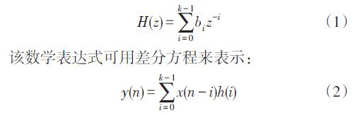
Where x(n) is the input sample sequence; h(i) is the filter coefficient; k is the filter order; y(n) is the output sequence of the filter.
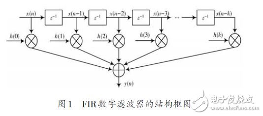
Figure 1 is a block diagram showing the structure of a k-order FIR digital filter.
2 FIR digital filter design flow
The design process mainly involves the development and design of tool software such as Matlab/Simulink, DSPBuilder and Quartus II. The entire design process, from system description to hardware implementation, can be done in a complete design environment, as shown in Figure 2.
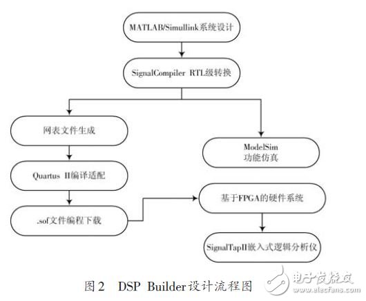
(1) Design input in Matlab/Simulink, that is, create a model file with the extension mdl in Matlab's Simulink environment, and graphically call the graphics module (Block) in Altera DSP Builder and other Simulink libraries to form system level or Algorithm level design block diagram (or Simulink design model).
(2) Using Simulink's graphical simulation and analysis functions, analyze the correctness of this design model and complete the model simulation, also called system level simulation.
(3) A key step in the DSP Builder design and implementation, the Signal file is converted into a general hardware description language Verilog file through Signal-Compiler.
(4) The converted Verilog source code is functionally simulated with ModelSim software to verify the correctness of the Verilog file. The next few steps are to synthesize, compile, and adapt the Verilog RTL code and simulation files generated by the above design in the Quartus II tool software. The sof file is loaded into the FPGA hardware system.
3 FIR digital filter detailed design
3.1 FIR digital filter module design and system level simulation
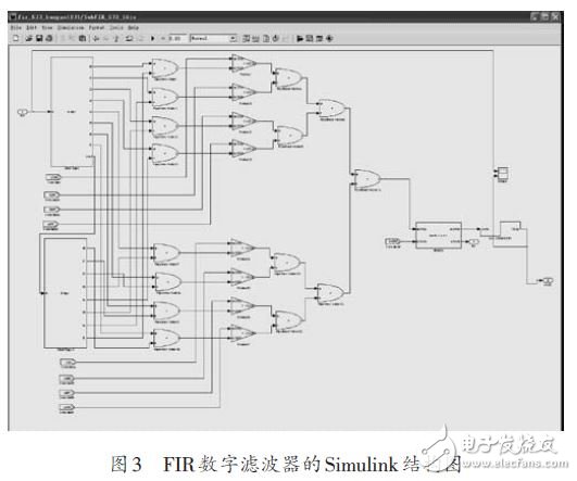
According to the principle of FIR digital filter, a 16-order FIR digital filter structure is built in the Simulink environment, as shown in Figure 3.
In the model construction process, two 8-bit Shift Taps shift register modules are used to decompose the input signal, and then the algorithm is calculated according to the principle of the digital filter.
surefire Flashlight Battery, fenix flashlight battery, streamlight flashlights, samsung flashlight battery,
mag light battery, black light flashlight battery, uv flashlight, pelican flashlights, brightest LED Flashlight Battery,
flashlight walmart battery, flashlight parliament battery, super bright flashlight, maglite flashlight battery,
high lumen flashlight battery, flashlight amazon battery, camera flash light battery, keychain flashlight battery,
ultrafire flashlight battery, flashlight battery home depot, tactical light battery, stinger flashlight battery,
mini flashlight battery, best Rechargeable Flashlight Battery, dorcy flashlight battery, cree flashlight battery.
Flashlight Battery
Flashlight Battery,LED Flashlight Battery,Flashlight LED Battery,Rechargeable Flashlight Battery
Asarke Industry Co., Limited , https://www.asarke-industry.com