CATV minimum loss attenuator for 75Ω measurement
Abstract: The CATV system for cable TV based on 75Ω characteristic impedance is tested with a 50Ω laboratory test device. Using a minimum loss impedance conversion circuit (MLP) of 75Ω to 50Ω is a broadband method for accurately measuring power and voltage. This article introduces the resistance network required for a minimum loss impedance conversion circuit. At the same time, the minimum loss impedance conversion circuit equation derived from the usual signal source and load impedance is given.
IntroductionThe minimum loss impedance conversion circuit can be used to measure broadband 75Ω circuits such as CATV tuning ICs, cable upstream amplifiers, and satellite DBS tuning ICs using 50Ω test equipment. When using the minimum loss impedance conversion circuit, you must know whether to use the voltage loss or power loss of the MLP. Due to impedance conversion, the amount of power loss in a minimum loss impedance conversion circuit is different from voltage loss. Obviously, the power loss used for power measurement and the impedance conversion from any direction are the same. The voltage loss used for voltage measurement differs depending on the direction of impedance transformation.
Summary of MLP characteristics from 75Ω to 50Ω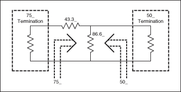
Figure 1. 75Ω to 50Ω minimum loss impedance conversion circuit
Figure 1 shows the conversion of 75Ω to 50Ω MLP. The 75Ω 'end can be regarded as a resistance network of a 75Ω device. Similarly, the 50Ω terminal can be regarded as a resistance network of a 50Ω device.
Table 1 shows that the value of power attenuation is the same when changing from 75Ω to 50Ω or from 50Ω to 75Ω. However, the value of voltage loss when changing from 75Ω to 50Ω is greater than the value of voltage loss when changing from 50Ω to 75Ω.
Table 1. Power and voltage losses of 75Ω to 50Ω minimum loss impedance conversion circuit.
| MLP Impedance TransformaTIon (Ω to Ω) | Power Loss (dB) | Voltage Loss (dB) |
| 75 to 50 | -5.72 | -7.48 |
| 50 to 75 | -5.72 | -3.96 |
| (50 to 75) + (75 to 50) | -11.44 | -11.44 |
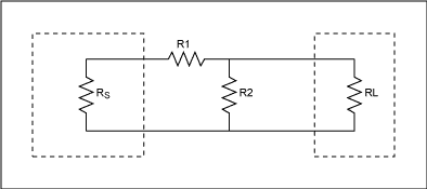
Figure 2. Minimum loss impedance conversion circuit
Figure 2 shows the minimum loss impedance conversion circuit with signal source impedance RS and load impedance RL. An L-type attenuator is used to match high impedance RS to low impedance RL. (Figure 2 assumes RS> RL.) The resistance value of this minimum loss impedance conversion circuit is determined by Equation 1 and Equation 2 [1]. 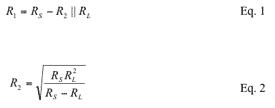
The signal path of the minimum loss impedance conversion circuit shown in Figure 3 is from high impedance to low impedance, that is, from the left side to the right side of the circuit. 
Figure 3. The signal path of the minimum power attenuator from high impedance to low impedance.
In the CATV system, the signal level is measured by the voltage unit dBmV [2], that is, the decibel value relative to 1mV. When the signal level is expressed by the voltage unit, the voltage loss of the MLP is used. According to Figure 3, the following common derivations are derived MLP voltage loss equation, and assume RS> RL.
According to Figure 3: 
The voltage loss is expressed in dB as: 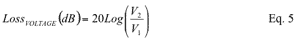
Substitute Equation 4 into Equation 5: 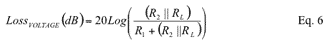
Equation 6.1 is the voltage loss equation expressed by RS and RL, which is the result obtained by substituting Equation 1 and Equation 2 into Equation 6. 
When the signal level uses power units such as dBm, MLP power loss is used. dBm is the decibel value relative to 1mW. The unit for measuring the signal level of a typical test device is dBm.
The equation for MLP power loss comes from the following, Figure 3 and Figure 4, assuming RS> RL. The original equation indicates that the power loss consists of voltage plus a resistance ratio. The power loss can be calculated by the ratio of the delivered power to the available power [3] [4]. 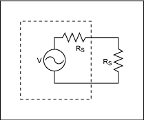
Figure 4. Available power that perfectly matches the load
Available power, PA, is the power obtained when the load is fully matched, as shown in Figure 4. 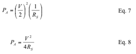
As can be seen from Figure 3, the power delivered to the load, PD, is: 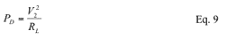
V2 can be expressed as: 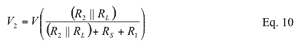
Substitute Equation 10 into Equation 9: 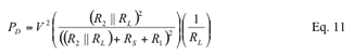
The power loss can be expressed in dB as: 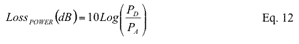
Substitute Equation 8 and Equation 11 into Equation 12: 
According to Figure 3, for a perfectly matched MLP: 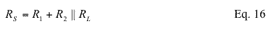
Substitute Equation 16 into Equation 15: 
Compare Equation 18 and Equation 6 to observe the difference between power loss and voltage loss. The power loss is equal to the voltage loss plus a logarithmic sum of the impedance ratio terms.
Equation 18.1 is the power loss equation expressed by RS and RL, which is the result of substituting Equation 1 and Equation 2 into Equation 18: 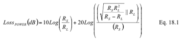
In order to maintain the consistency of the discussion when discussing the signal path from low to high impedance, the position of RS and RL in the circuit shown in Figure 5 is the same as that in Figure 3, although the signal now passes through the MLP in the opposite direction. 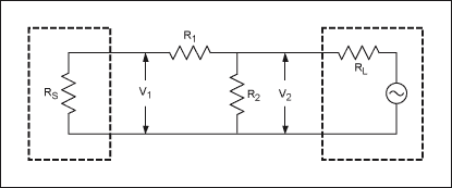
Figure 5. MLP from low-impedance to high-impedance signal path
According to Figure 5: 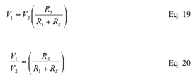
The voltage loss can be expressed in dB as: 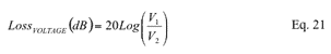
Substitute Equation 20 into Equation 21: 
Use RS and RL to express the equation of voltage loss, that is, substituting Equation 1 and Equation 2 into Equation 22. 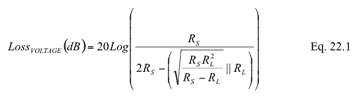
From Figure 5, the power loss matched to the signal source and load impedance: 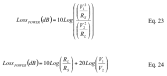
Substitute equation 20 into equation 24. 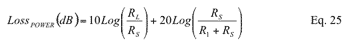
Still using only RS and RL to express the power loss equation, substituting Equation 1 and Equation 2 into Equation 25. 
Compare Equation 25 and Equation 22 to observe the difference between the power loss and voltage loss equations. For the signal path from low resistance to high resistance, the power loss is equal to the logarithm of the voltage loss and the resistance ratio.
The resistance value of the minimum loss impedance conversion circuit of 75Ω to 50Ω can be determined by referring to the equation of MLP shown in FIG. 2 above. Select RS and RL to be 75Ω and 50Ω respectively. This also satisfies the assumption of RS> RL. 
From Equation 1: 
Use Equation 6 to determine the voltage loss of the 75Ω to 50Ω signal path. 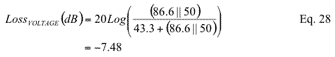
Use Equation 18 to determine the power loss of the 75Ω to 50Ω signal path. 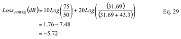
Use Equation 22 to determine the voltage loss of the 50Ω to 75Ω signal path. 
Use Equation 25 to determine the power loss of the 50Ω to 75Ω signal path. 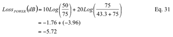
Note that the power loss is the same when the signal passes in either direction, but the voltage loss differs depending on the signal direction. Similarly, the difference between power loss and voltage loss is attributed to the difference in resistance ratio terms.
The power loss and voltage loss of the minimum loss impedance conversion circuit are different due to the difference between the signal source impedance and the load impedance. Power loss is equal to the logarithmic sum of voltage loss and a resistance ratio term.
When the signal passes in either direction, the power loss is the same. However, when the signal goes from a high-impedance signal source to a low-impedance load, the voltage loss is much larger.
When making dBmV, dBµV or dBV or any voltage-related measurements, use voltage loss. When making dBm or any power-related measurements, use power loss
Apple Lightning , Micro USB And Type-C
Charging Cable Micro Usb,Charging Cable Extension,Charging Cable Magnetic,Garmin Charging Cable Usb
Hebei Baisiwei Import&Export Trade Co., LTD. , https://www.baisiweicable.com