1 Digital front end
The low-power digital receiver is mainly for voice signals, and the signals to be processed are all narrowband. The analog narrow-band intermediate frequency signal sent by the mixer in the digital front end is sampled to generate a digital narrow-band intermediate frequency signal. Before demodulating the signal, first move the spectrum to zero intermediate frequency, and then perform filtering, downsampling and other processing, as shown in Figure 1.
In Figure 1, A / D represents the analog-to-digital converter, LPF represents the low-pass filter, fs represents the sampling rate, and fo represents the intermediate frequency closest to the mirror image at zero frequency. Among them LPF realizes the function shown in Fig. 2. Let the sample rate of the filtered complex signal be reduced to f's = fs / M.
In FIG. 2, the thin line indicates the upper sideband (USB), and the thick line indicates the lower sideband (LSB).
To illustrate, in practice, the positional relationship between the upper and lower sidebands can only be determined based on the intermediate frequency of the analog signal and the sampling rate fs. For convenience of explanation, the LSB is considered to be on the left and the USB is on the right.
2 Demodulation scheme one
Taking the demodulation upper sideband as an example, as shown in Fig. 3, a digital bandpass filter is designed, whose frequency response is symmetrical about the center frequency fo ',
Regardless of f3, f4, the attenuation at the cutoff frequency is at least -20 dB.
The design steps of the band-pass filter are as follows:
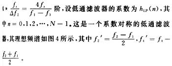
(1) First design a low
Pass filter, the passband bandwidth is Δf1 = f2-f1, and the transition band bandwidth is Δf2 = f1-f3. Estimate filter order: N =
(2) The band-pass filter (BPF) can be realized by spectrum shifting the above-mentioned low-pass filter, as shown in FIG. 5. Therefore the filter coefficients:
(3) If the FIRS instruction is used to implement the sideband filter, the execution time of the sideband filter will be reduced to half of the original. But this time requires that the filter coefficients are symmetrical. The aforementioned low-pass filter coefficients are symmetrical.
GreenTouch infrared touch screen uses the high quality of transparent glass so it has excellent clarity, resolution, light transmittance and reliability. Even though there are some scratches on the surface of glass,it can still work normally. The surface of the screen has no surface coating on the plastic film or moving parts, so there is no parts will wear consumption during the usage.infrared touchscreen ensures stable performance without any ghost spots or drift.The operation is sensitive, through finger, glove, passive stylus and other opaque objects can perform accurate touch input. a high-precision IR Touch Screen.
Pictures show:


Multi Point Infrared Touch Screen,Smart ​Infrared Touch Screen,Infrared Touch Frame Technology,Touch Screen Frame For Tv,Infrared Touch Screen Panel,IR Touch Screen
ShenZhen GreenTouch Technology Co.,Ltd , https://www.bbstouch.com