1 Introduction
In embedded systems, especially data acquisition systems, real-time is crucial. Not only does it require an embedded microprocessor to respond quickly, it also requires an embedded system to process data in a timely manner [1]. In the data collection system designed in this paper, if the conventional method is used to transfer data, when the speed of data collection is high, because the Windows CE system and the collection system cannot be synchronized, it may cause data loss, making the system unable to transmit data in a timely and accurate manner . To solve this problem, you can use the built-in first-in first-out (FIFO) buffer on the acquisition board. At present, there is no report on the domestic literature on the realization of FIFO in the Windows CE system. In this regard, this article discusses how to develop the driver of the FIFO-based data acquisition board on the Windows CE.net platform to ensure the accuracy of the data acquisition data. Comparing conventional methods with FIFO through experiment, get better results
2. System software and hardware platform
Embedded systems are widely used in many fields such as communication, control and consumer electronics because of their small size, strong pertinence, and good real-time characteristics. The operating system in this design is Windows CE.net, a real-time operating system specially designed for embedded systems introduced by Microsoft. It is a 32-bit, multi-threaded, multi-tasking embedded operating system. With its modular structure, Good real-time capability, strong communication capabilities and support for multiple CPUs have good application prospects in various industrial control, consumer electronics and other fields [2].
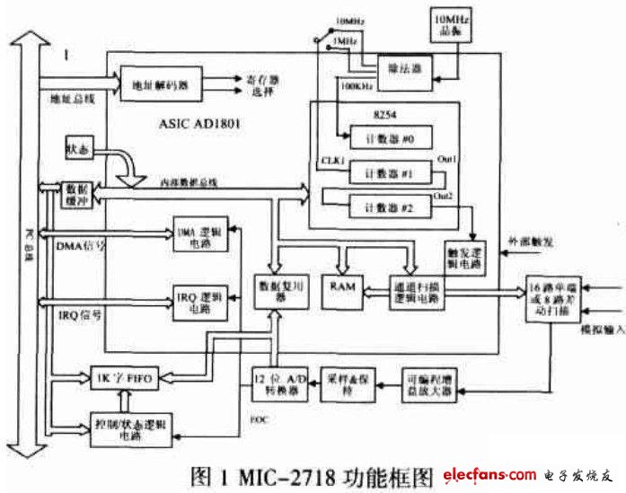
The hardware platform of the data acquisition system is Advantech's MIC-2000 industrial control computer. MIC-2000 has good mechanical reliability and bus expansion capability [3], and can be used in harsh industrial sites. The data acquisition board is an analog input board MIC-2718. It is a high-gain, high-performance multi-function data acquisition board. It provides a programmable gain amplifier that allows users to collect very small input signals without the need for external power. The built-in 1K word FIFO buffer ensures the speed and accuracy of data collection. MIC-2718 is a 12-bit 100KHz A / D module. It supports 16 single-ended or 8 differential inputs. The maximum conversion time is 8usec. There are three methods: software trigger, timer trigger and external trigger. The functional block diagram of MIC-2718 is as follows Figure 1.
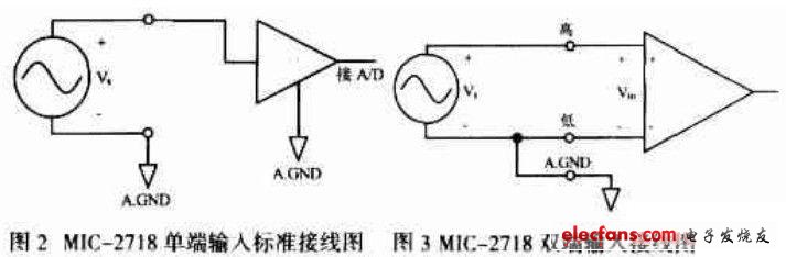
MIC-2718 supports jumper selection of 16 single-ended inputs or 8 differential inputs. When single-ended input is selected, only one signal line needs to be connected to each channel, and the signal reference ground is the common ground on the board [4]. The standard wiring diagram is shown in Figure 2. When double-ended input is selected, there are two signal lines for each channel. MIC-2718 measures the voltage difference between the two analog signals. If the signal source is not grounded, it is called a "floating" signal source. 3 shows the wiring method.
3. Windows CE driver
Like other operating systems, Windows CE.net also provides drivers for many peripherals. The drivers connect the operating system and the device so that the operating system can identify the device and provide device services for the application [5]. However, for unconventional hardware devices (or unconventional for existing Windows CE application systems), Microsoft does not provide drivers, so the hardware manufacturers of the devices need to provide WndowsCE drivers, or users themselves develop [6] . At present, there is no driver for MIC-2718 based on Windows CE.net 4.2, so it needs to be developed by itself.
The two modes of the Windows CE.net driver are local driver and stream interface driver [7]. The local device driver is suitable for integration into devices based on the Windows CE.net platform, such as general LED drivers and power drivers. The stream interface driver model is suitable for any I / O device (any peripheral device that generates or consumes data streams as its main function) logically regarded as a data source or data storage device [8], so it is in the acquisition system , WinCE peripheral device drivers generally have more stream interface drivers. In addition, most of the peripheral device drivers can be mapped as stream interface drivers. Regardless of the type of device controlled by the driver, the stream interface driver uses the same interface and derives a set of identical functions (stream interface functions).
According to the characteristics of the data acquisition system and the driver model in Windows CE in this paper, this design uses a stream interface driver model.
PufangTech`s UHF Radio Modem operates in 403~433MHz, 419~440MHz, 450~480MHz and 480~512MHz frequency band. These radio modems have air data rate of 19200bps in 25kHz channel spacing and 9600bps in 12.5kHz. These UHF radio modems work in transparent transmission, and they can ensure compatibility to most user systems and protocols. You can also change the settings in the programming mode with a Windows based program on PC.
Wide band radios can run and be achieved with higher frequencies over 1GHZ, however, this is not likely to meet the standard of range and reliability as a wide band link.
PufangTech`s UHF radio modems are perfect for SCADA, remote control and telemetry for utility distributions (water, electricity, oil & gas).
UHF Radio Modem
UHF Radio Modem,UHF Modem,UHF Data Radio Modem,Radio VHF UHF
Shenzhen PuFang Technology Co., Ltd. , https://www.hytelus.com