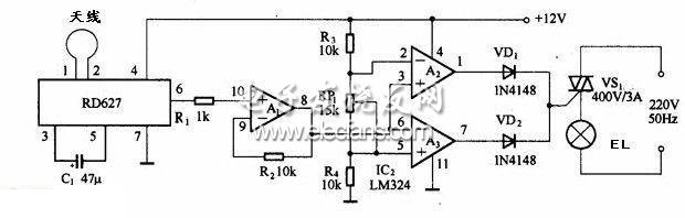
The operational amplifier A1 is used to amplify the output signal of the foot of RD627â‘¥, and the amplified signal is sent to the window comparator composed of operational amplifiers A2 and A3. The reference voltage of the window comparator is provided by the voltage divider of R3, RP1 and R4. When static, both op amps A2 and A3 output low level, the bidirectional thyristor VS1 is cut off, and the light bulb EL is off; when someone enters the antenna coverage area, the dynamic signal output from the foot of RD627 is sent to the window comparator for detection Point, make A2 or A3 output high level, VD1 or VD2 turn on, trigger the bidirectional thyristor VS1 turn on, the light bulb EL is lit, when people leave the antenna coverage, A2 or A3 output will return to low level , The bidirectional thyristor VS1 ends, and the light bulb EL goes out. Principle circuit of microwave sensor automatic lamp based on RD627:
Electric Spiral Stove,Cooking Plate Stove,Electric Cook Stove,Spiral Hot Plate Electric Stove
Shaoxing Haoda Electrical Appliance Co.,Ltd , https://www.hotplates.nl