BA1404 is one of the few FM transmitting integrated circuits, which makes up for the shortcomings of designing FM circuits with discrete components in the past, and has the function of stereo modulation. Only a few external components can get a beautiful stereo FM signal. Therefore, it has important application value in FM stereo emission and wireless microwave.
1. Main features of BA1404
The main features of BA1404 are as follows:
â— Using low voltage and low power consumption design, the voltage is between 1 and 3V, the typical value is 1.25V, the maximum power consumption is 500mW, and the quiescent current is 3mA;
â— Integrated stereo modulation, FM modulation, radio frequency amplifier circuit on one chip;
â— Less peripheral components required;
â— High separation between two channels, typical value is 45dB;
◠The input impedance is 540Ω (fin = 1kHz), the input gain is 37dB (Vin = 0.5mV);
â— The typical RF output voltage is 600mV.
2. Pin function and working principle
BA1404 is mainly composed of pre-amplifier (AMP), stereo modulator (MPX), FM modulator and RF amplifier.
The stereo front stage is an audio amplifier with two channels. When the input is 0.5mV, the gain is as high as 37dB, and the bandwidth is 19kHz. If there is a component with a frequency higher than 19kHz in the input signal, a low-pass filter must be added to the input, otherwise the separation of the two channels will decrease.
In the stereo modulation group, the 38kHz signal output by the oscillator is modulated in stereo. Usually an adjustable resistor is connected to pins 16 and 17 to obtain the best channel separation.
The modulated signal synthesized by the stereo mixed signal (MPX output signal) and the pilot output signal (PILOT OUT) enters the RF oscillator through pin 12 and performs FM modulation on the carrier wave. The RF signal is amplified and the RF signal is output. The typical value of the RF signal is at Around 600mV.
BA1404 also provides a reference voltage unit VREF. The designer can use this voltage signal to change the capacitance value of the external varactor diode, and then change the oscillation frequency of the carrier. Therefore, as long as the voltage division value of a resistor is controlled, the purpose of changing the transmission frequency can be achieved, which is a relatively unique design.
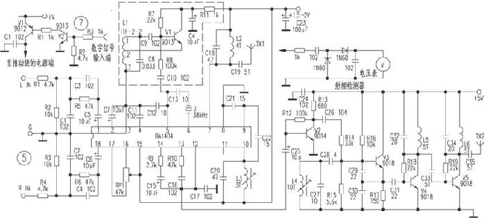
3. Typical applications
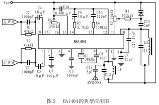
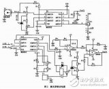
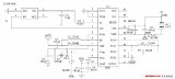
The picture shows the typical application circuit of BA1404. In the figure, the left and right channels input audio signals into the BA1404 through a pre-emphasis circuit. The internal reference voltage is used to change the capacitance value of the varactor diode, thereby realizing the adjustment of the transmission frequency.
Pay attention to the following points when designing:
(1) In order to make the frequency response of the transmitter and FM receiver match each other, a pre-emphasis network needs to be added at the input end, and its time coefficient is 50 μs.
(2) At the 13th and 14th feet, when the stereo mixed signal and the pilot signal output by the stereo modulator are combined, the separation of the stereo channels may be deteriorated, so you must pay attention to the values ​​of the peripheral components of the 12, 13, and 14th feet.
(3) If the output frequency range of the OSC oscillation network is within 76-108MHz, it can be wound around 2.5 turns with a 0.5mm enameled wire on a 5mm iron core, so that the capacitance value of C11 is 47pF. The same should be true for the RF matching network on pin 7.
(4) In order to simplify the application, the following measures can be taken:
â— Leave feet 16 and 17 in the air. Because the channel separation has been ensured within the integrated block, the adjustable resistor is only for optimization.
â— No need to fine-tune the transmission frequency of the varactor diode, directly short circuit at the varactor tube, so that R3 and D1 can be omitted.
â— You can omit the RF matching network on pin 7 and connect directly to VCC.
The emission range of the BA1404 application circuit shown in the figure can reach hundreds of meters. If you want to increase its emission distance, you can add an RF amplifier to the RF output, you can use discrete components, or you can directly choose RF from MAXIM. Power amplifier circuit MAX2611 or MAX2650, they are suitable for matching with BA1404.

Follow WeChat

Download Audiophile APP

Follow the audiophile class
related suggestion
This article mainly introduces the infrared diode emission circuit diagram (acoustic and optical alarm / TPS604 / wireless headset infrared emission circuit in detail). Wireless Headphones...
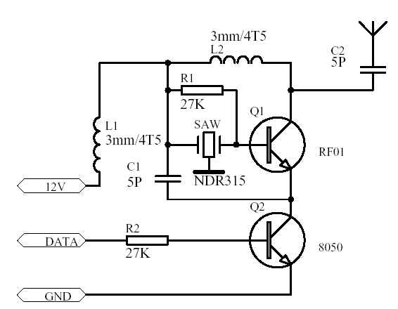
This article mainly introduces the 315m wireless transmission and reception circuit diagram (wireless transmission / wireless reception circuit diagram in detail). The radio remote control circuit consists of radio ...
This article mainly introduces the 1000 meters wireless transmission circuit diagram Daquan (single tube oscillation C8050 / high frequency triode / T630 FM transmission circuit ...
The ultrasonic generator consists of two piezoelectric plates and a resonance plate. When a pulse signal is applied to its poles, and its frequency is equal to the natural oscillation of the piezoelectric chip ...
In order to improve the communication and information exchange capabilities of modern weapon systems in harsh electromagnetic environments, make full use of the natural secrecy of the laser and reduce the radio frequency ...
The NPX I chip has 4 KB of user programmable space, 4 KB of custom ROM, and a 2D LF input stage. Various sensors ...
The system selected is the AT89C51 chip of the 51 series. AT89C51 is a programmable erasable read-only storage with 4k byte flashing ...
The tire module circuit uses the intelligent embedded sensor MPXY8300 of FREESCALE. This series of sensors integrates the company's ...
The following figure is the schematic diagram of the wireless remote control transmitter and receiver circuit. Figure 1 The schematic diagram of the wireless remote control transmitter circuit. Figure 2 The schematic diagram of the wireless remote control receiver circuit.
The transducer transmits and receives ultrasonic waves directly below the bottom of the ship to detect targets under the bottom of the ship. The difference is that the former uses fish as the main detection ...
The four-way remote control transmitter circuit is mainly composed of a 315MHz wireless data transmission module and a code integrated PT2262.
Electronic enthusiasts provide you with a remote control toy car launch circuit, hoping to inspire your creativity.
The video signal is firstly amplified by a reverse phase, and then input to the AM modulation stage through the emitter follower; the transmission frequency is generated by the LC high-frequency oscillator and sent to the AM modulation ...
BA1404 Stereo FM transmitter circuit (power amplifier, field strength circuit)
LM317 AFM transmitter Transmitter circuit made by LM317
2m FM 144M-148M transmitter circuit Near-Earth Telemetry (Morse Code ...
This SMD FM transmitter has ...
4W FM transmission circuit diagramTECHNICAL CHARACTERISTICS: Stabilise ...
Ultrasonic transmission circuit design of low-voltage power supply Ultrasonic application fields are very broad, such as military sonar technology, industrial nondestructive testing, testing ...

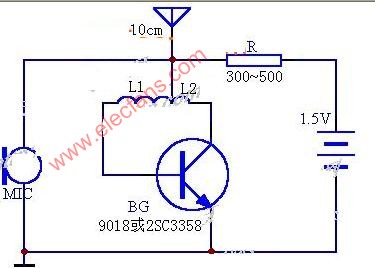
Simple FM transmitter circuit 1.5V-10m3V-30m working current: <= 0.5mA24 # enameled wire at 0.6c ...
96Mhz FM transmitter circuit diagram
56M video image transmission circuit diagram The radio frequency transmission circuit generates a frequency of 56MHz through a three-point capacitor, and the image signal is collected by the camera ...

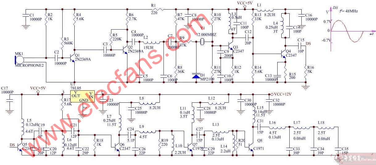
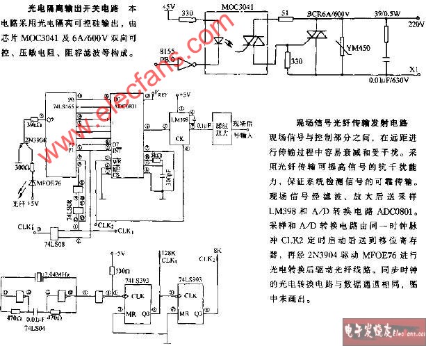
On-site signal fiber transmission transmitter circuit
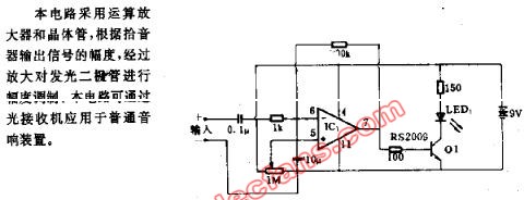
Voice modulation optical transmission circuit
50khz frequency light emitting circuit
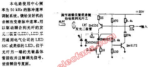
Figure 3 is a practical 50m FM wireless headset transmitter part of the circuit. The circuit is divided into
â—† Overview of circuits Many homes now have televisions
![[Photo] Practical home TV station transmission circuit](http://i.bosscdn.com/blog/20/06/41/719132274.jpg)
The working voltage is 9V, the working current is 2 ~ 6mA, the component parameters are as shown in the figure, BG1 ...
The low-power FM transmitting circuit introduced in this article, due to the use of a dedicated transmitting tube, the degree of modulation ...
![[Photo] AM audio transmission circuit](http://i.bosscdn.com/blog/20/06/41/5205911625.gif)
![[Photo] Remote FM transmitter circuit made with LM389](http://i.bosscdn.com/blog/20/06/41/5205320565.gif)
![[Photo] 8050 single tube launch circuit](http://i.bosscdn.com/blog/20/06/41/5205224485.gif)
3-Meter Zender (100-108Mhz / 10-15 ...
![[Photo] 100-108Mhz / 10-15W launch ...](http://i.bosscdn.com/blog/20/06/41/5205040737.gif)
For an amateur radio enthusiast, getting a good FM transmitting circuit is like picking up ...
![[Photo] 1000-meter single-tube oscillation (C8050) FM transmission ...](http://i.bosscdn.com/blog/20/06/41/5204719922.gif)
BA1404
![[Photo] BA1404 modulator circuit](http://i.bosscdn.com/blog/20/06/41/520458107.jpg)
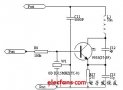
The working voltage of this circuit is 9V, working ...
![[Photo] Simple frequency modulation transmitting circuit with stable frequency](http://i.bosscdn.com/blog/20/06/41/520451129.jpg)
The author refers to the "simple and easy-made integrated FM speech" published in the 21st issue of "Electronic Newspaper" in 1993 ...
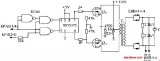
![[Photo] BA1404 / 1404F FM stereo transmission ...](http://i.bosscdn.com/blog/20/06/41/520409234.gif)
'+ data.data.username +' '; dom + ='
Pole Height: Hot-Dip Galvanized, Q235 Painting Plastic,4M-15M For Choosing
Pole And Lamp Fixture Color: Grey, White, Black, Blue, Green, EtcPole Shape: Tapered, Square, Hexagonal, Octagonal, Etc
Testing Including:
1.Material testing
2.Shape testing
3.testing after Galvanizaiton
4. Tensile testing
5.Fittings check


Steel Pole
Steel Pole,Galvanized Steel Pole,Street Lamp Steel Pole,Steel Solar Street Light Pole
Yangzhou Bright Solar Solutions Co., Ltd. , https://www.cnbrightsolar.com