Although the output voltage may be higher or lower than the input voltage, peak current mode controlled discontinuous buck-boost converter is a good choice for LED drivers. However, when this type of buck-boost converter is used to design a driver, the change in LED voltage will change the LED current, and an open LED will cause an excessively high voltage at the output, thereby damaging the converter. This article will discuss in detail the design of this converter for LEDs, and give a variety of ways to overcome its inherent shortcomings.
Light-emitting diodes (LEDs) have been used for many years. With the advancement of the latest technology, they are gradually becoming strong competitors in the lighting market. The new high-brightness LED has a very long life (about 100,000 hours) and high efficiency (about 30 lumens / watt). Over the past three decades, the light output brightness of LEDs will double every 18 to 24 months, and this growth momentum will continue. This trend is called Haitz's Law, which is equivalent to Moore's Law of LEDs.
Electrically speaking, LEDs are similar to diodes, they are also unidirectionally conductive (although their reverse blocking capability is not very good, high reverse voltages are easily damaged (LED), and have low dynamics similar to conventional diodes Impedance VI characteristics. In addition, LEDs generally have a rated current when they are safely turned on (the rated current of high-brightness LEDs is generally 350mA or 700mA). When the rated current is passed, the difference in LED forward voltage drop may be relatively large, usually 350mA white light The voltage drop of the LED is between 3 and 4V.
Driven LEDs require controlled DC current. In order to make the LED life longer, the ripple in the LED current must be very low, because the high ripple current will cause the LED to produce larger resistive power consumption and reduce the LED life. LED drive circuits require higher efficiency, because the overall efficiency depends not only on the LED itself, but also on the drive circuit. The switching converter working in the current control mode is an ideal driving scheme to meet the high power and high efficiency requirements of LED applications.
Driving multiple LEDs also requires careful consideration. Figure 1 is a series-parallel connection circuit of LEDs. Figure 1 (a) is the parallel connection circuit of LEDs. Figure 1 (h) is a series connection circuit of LEDs. Because the dynamic impedance and forward voltage drop of each LED are different, it is impossible to ensure that the current flowing through the LED is the same if there is no external current sharing circuit (such as current mirroring); in addition, the failure of one LED will make the LED string The disconnection causes all LED current to be distributed among the remaining LED strings, which will cause an increase in the current on the LED strings, which may damage the LEDs. Therefore, for the above two reasons, parallel LED circuits as shown in Fig. 1 (a) are generally not used in the design.
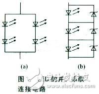
Therefore, it is better to connect the LEDs in series. But the disadvantage of this method is that if one LED fails, the entire LED string will stop working. A simple way to keep the remaining LED strings working is to connect a Zener diode (whose rated voltage is greater than the highest voltage of the LED) in parallel with each (or each group) LED, as shown in Figure 1 (b). In this way, after any LED fails, its current will flow to the corresponding Zener diode, and the rest of the LED string can still work normally.
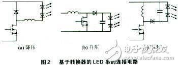
Basic single-stage switching converters can be divided into three categories: buck converters, boost converters, and buck-boost converters. When the voltage of the LED string is lower than the input voltage, the buck converter Figure 2 (a) is the ideal choice; when the input voltage is always lower than the string output voltage, it is more appropriate to use a boost converter Figure 2 (b) ; When the output voltage may be higher or lower than the input voltage (caused by the output or input changes), it is more appropriate to use the buck-boost converter Figure 2 (c). The disadvantage of the boost converter is that any transients in the input voltage (which can increase the input voltage and exceed the output voltage) will cause a large current to flow through the LED (due to the low dynamic impedance of the load), thereby damaging the LED. The buck-boost converter can also replace the boost converter, because the transient of the input voltage will not affect the LED current.
Working principle of buck-boost converter
For LED drivers in low voltage applications, a buck-boost converter is a good choice. The reason is that they can drive the LED string with higher and lower input voltage (boost and buck), high efficiency (easy to reach more than 85%), discontinuous operation mode can suppress the change of input voltage (provided Excellent line voltage regulation), peak current control mode allows the converter to regulate the LED current without complicated compensation (simplified design), it is easy to achieve linear and PWM LED brightness adjustment, switching transistor failure will not damage the LED, etc. Figure 2 shows the connection circuit of the buck, boost and buck-boost converter and the LED string.
However, this method still has shortcomings: First, the peak current control problem, because the use of discontinuous current mode buck-boost converter is a constant power converter. Therefore, any change in the LED string voltage will cause a corresponding change in the LED current; another problem is that the LED open circuit state will produce a high voltage in the circuit that damages the converter; in addition, additional circuits are needed to convert the constant power converter to constant Current converter and need to protect the converter under no-load conditions.
Figure 3 shows the specific application circuit of the buck-boost converter. The controller has a built-in oscillator for setting the switching frequency. At the beginning of the switching cycle, Q1 turns on. As the input voltage VIN is added to the inductor, the inductor current (iL (t)) starts to rise from zero (initial steady state). When the induced current rises to the preset current value (ipk), Q1 turns off. The switch on time (ton) is determined by the following formula:
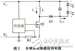
ton = ipkL / VIN
At this time, the total energy (J) stored in the inductor is:
J = Li2pk / 2
In this way, although the switch will be closed at this time, the current flowing through the inductor will not be interrupted. This will turn on the diode D1 and generate an output voltage (-Vo) across the inductor. This negative voltage will cause the inductor current to drop rapidly. After a certain time tOFF, the inductor current tends to zero. This time can be calculated by the following formula:
tOFF = ipkL / VO
In order for the converter to operate in discontinuous conduction mode, the sum of the switch on-time and the inductor current fall time must be less than or equal to the switching period TS to ensure that the inductor current can start from zero during the next switching period.
In fact, in the case of minimum input voltage and maximum output voltage, (tON + tOFF) can achieve the maximum value. Therefore, ensuring that the converter operates in discontinuous conduction mode at these voltages can ensure that the conditions listed in the following formula are met under any circumstances: tON + tOFF≤Ts
The product of the power (Pin) inductance obtained by the converter from the input terminal and the product of the switching frequency f: namely:
Pin = fsLi2pk / 2
Assuming that the LED string voltage (VO) is constant and the efficiency is 100%, then the LED current (iLED) is:
iLED = PIN / VLED = Li2pkfs / 2V
In peak current control mode, ipk is usually a fixed value. Therefore, the LED current is completely independent (in theory) from the input voltage. At a fixed ipk, the rise (fall) of the input voltage will cause the conduction time of the transistor to decrease inversely (increasing), which will provide good line voltage regulation. In practical applications, the delay between the detection of the current peak by the control IC and the actual turn-off of the GATE pin will cause a change in the input power. Shorter on-time will cause more errors due to the delay time, because the delay time will account for a considerable part of the on-time.
In fact, the LED current is inversely proportional to the voltage of the LED string. A circuit with a nominal output of 20 V and 350 mA will generate 700 mA at a 10 V output voltage, which is obviously not the desired result. However, by making the switching frequency proportional to the output voltage, the above formula provides a method for converting a constant power converter to a constant voltage converter.
Assuming fs = KVO, where K is a constant, then:
iLED = kLi2pk ï¼ 2
In this way, iLED will be independent of input and output voltage.
Another disadvantage of the flyback converter is that it is susceptible to the output open state. When the LED is open, the energy stored in the inductor will be transferred to the output capacitor at the end of each switch on-time. In this way, a load that lacks a capacitor discharge will cause the voltage across the capacitor to gradually rise, eventually exceeding the device's nominal value and damaging the power stage. Therefore, an additional circuit can be added to provide output voltage feedback and overvoltage protection.
More than 10 years we are professional in manufacturing the single color Led Display in Shenzhen, China. We provide customized single color LED display board, and the single color LED display screen with excellent brightness and color performance, which are prefered by customers worldwide. According to customers' requirement, our Outdoor Single Color LED Display and Indoor Single Color LED Display can provide two ways of broadcasting, synchronous and asynchronous.


Single Color Led Display,Led Single Color Display,Single Color Matrix Led Display,Led Board Display
Shenzhen Joy LED Display Co., Ltd. , https://www.joe-led.com