Design of Brushless DC Motor Controller Based on LIN Bus
1 Introduction With the continuous improvement of the electrification and automation of automobile parts and the high requirements on the noise, electromagnetic compatibility and efficiency of automobile motors, permanent magnet brushless DC motors are gradually replacing brushed permanent magnet DC motors. The permanent magnet brushless motor has the advantages of small size, long life, high efficiency, simple structure, good reliability and so on. Using it as a driving actuator for automobile parts can effectively improve the performance of automobile parts. For example, in Freightliner's M2 series of commercial vehicles, a brushless motor is used to drive the blower of its air conditioning system to better adjust the air supply speed.
Due to the maturity of automotive bus technology, the control of multiple motor units in automobiles is changing from traditional centralized harness control to distributed bus control. Distributed bus control can reduce the wiring harness and reduce the cost.It is convenient for each motor control unit and other electronic control units in the car to form a comprehensive and coordinated control system, improve the operational reliability of each control unit, reduce redundant sensors and corresponding soft Hardware configuration to realize information exchange and resource sharing. At present, the commonly used automotive bus includes CAN, LIN, etc., where LIN is oriented to the application of low-speed occasions. The author designs a brushless DC motor controller based on LIN bus. The controller is composed of MC68HC908MR16 single-chip microcomputer, PC33896 pre-driver and MC33399LIN transceiver introduced in the literature, and obtains good control performance at low cost.
2 Brushless DC motor control system based on LIN bus?
The LIN bus is a new type of low-cost automotive body bus.It was launched in 1999 by the LIN Association of European car manufacturers Audi, BMW, Daimler2Chrysler, Volvo, Volkswagen, VCT and other companies and semiconductor manufacturer Motorola.It has been in use since 2003. .
The LIN bus uses a serial communication protocol, which has the following characteristics: single-master multi-slave organization (that is, no bus arbitration); low-cost hardware implementation based on ordinary UART / SCI interface, low-cost software or as a pure state machine; slave The node can realize self-synchronization without quartz or ceramic resonator; guarantee the delay time of signal transmission; the low-cost single-line communication medium, the communication rate can reach up to 20kb / s. A LIN network consists of a master node and no more than 15 slave nodes. All nodes have a slave task. The slave task is divided into a receiving task and a sending task. The master node also has a master task. The communication on the LIN network is always initiated by the master task.The master task transmits the message frame header.The message frame header includes the synchronization interval field, synchronization field and marker field; the slave task makes a message response, and the message response includes 2 , 4 or 8 bytes of data field and check field, message frame header and message response form a complete message frame.
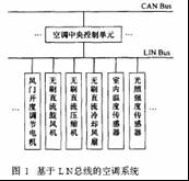
As the complement of CAN bus, LIN bus is mainly used for body control. The main connection objects of the body network are seats, doors, air conditioners and instrument display systems. The block diagram of the fully automatic air conditioning system based on LIN bus is shown in Figure 1. Among them, the air-conditioning central control unit plays the role of CAN / LIN gateway and LIN master node, and the other units are slave nodes, which are divided into sensor slave nodes and execution slave nodes. The sensor slave node sends environmental status values ​​such as temperature, humidity, and sunshine intensity to the master node.The master node makes comprehensive decisions based on these status values ​​and the parameters of the car's interior temperature set by the driver, and transmits control commands to the execution slave node. The node performs corresponding actions according to the command. Such an air-conditioning system effectively achieves distributed control of the nodes, reduces the number of wiring harnesses installed on the car, and at the same time realizes true fully automatic control, so that the various components of the air-conditioning system operate in harmony, so that the indoor temperature reaches and remains at the driver's set value. Create a comfortable indoor environment. Because the brushless DC motor has good speed regulation performance, some slave nodes in the air conditioning system use it as a driving component, such as a compressor, a blower, and a cooling fan. These slave nodes and the master node form a closed-loop control of the brushless DC motor speed based on the LIN bus.The master node gives the motor speed through a decision algorithm, and the speed feedback and control algorithm are completed by the slave node.The slave node is the author The controller to be designed.
3 Controller hardware structure
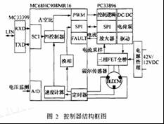
The structural block diagram of the controller is shown in Figure 2. The figure includes: power management module, MC68HC908MR16 single-chip microcomputer control module, PC33896 pre-drive module, three-phase FET full bridge module, MC33399LIN physical layer communication module.
The Hall sensor detects the position of the motor rotor. It is three signals with a pulse width of 180 ° (electrical angle) and a difference of 120 ° (electrical angle). The timer input capture unit of the single chip microcomputer captures the change of the position signal, realizes the commutation of the stator winding current, and ensures that the magnetic field generated by the stator maintains an average vertical relationship with the permanent magnet magnetic field of the rotor, so as to generate maximum torque. At the same time, the speed of the motor can be calculated through the time interval between the two commutations recorded by the timer. According to the difference between the target speed and the calculated speed, the PWM duty cycle is adjusted by the PI algorithm to control the motor speed. The target speed of the motor, start / stop, forward / reverse and other information come from the message frame of the LIN bus.
3.1 Power management module
The electrical load inside the modern car is constantly increasing. In the future, the 42V power system will replace the existing 12V power system. But to fully realize this transformation, there are still many problems that have not been solved, and now the main use of 42V / 12V dual power supply as a transition plan. The controller designed by the author takes this development trend into consideration. In 12V motor applications, the controller uses a single 12V power supply; in 42V motor applications, the controller uses a 42V / 12V dual power supply. At the same time, the power management module contains a 12V / 5V power voltage regulator chip LT1211.
3.1 SCM control module
The single-chip microcomputer control module is based on the MC68HC908MR16 single-chip microcomputer. It is an 8-bit single-chip microcomputer dedicated to motor control. The working temperature range reaches-40 ~ 105 ℃, fully adapted to the working environment in the car. The chip has a 12-bit, 6-channel PWM module, which generates 6-channel PWM logic signals (can be set to 6-channel independent or 3 pairs of two complementary); Timer A, 0, 1, 2 three channels are used to capture the position The change of the sensor signal, channel 3 is responsible for recording the moment when the position signal of channel 2 changes; 10-bit A / D converter, the conversion time is 16-17μs, can quickly complete the battery voltage monitoring task; error signal input, used to occur in An interrupt is generated in the case of overcurrent or overheating, and the PWM output is blocked; the unique fast 8-bit multiplication and 16-bit division instructions make it have higher computing power and can complete more complex control algorithms; 768B on-chip RAM and 16kB The on-chip Flash memory has online programming capabilities and security features; system protection features, including watchdog reset and low voltage reset prohibition, enhance the stability and reliability of the program.
3.3 Front drive module
The core of the pre-drive module is PC33896, which is a newly launched three-phase FET pre-driver dedicated to the 42V / 12V system of automotive electronics. The chip contains DC / DC step-down circuit, current sampling amplifier, SPI communication port and various protection circuits. PC33896 directly receives 6 PWM logic signals from the single chip microcomputer and converts them into drive signals for driving the gates of 6 FETs. If the power supply voltage of the automotive system is the new 42V power system, the on-chip DC / DC will reduce it to about 15V for FET gate circuit driving, saving the power dissipated by turning on and off the FET; if the car power supply The voltage used is the current 12V system. In some cases, the power supply voltage will not be enough to drive the FET gate. At this time, the charge pump circuit will raise it to at least about 10V to ensure the normal driving of the FET. The internal current sampling amplifier is used to measure the DC bus current. The single-chip microcomputer can send commands through the SP I port, configure the PC33896 (such as the operation of the DC / DC and charge pump, the magnification of the current amplifier, etc.) and diagnose its faults.
3.4 LIN physical layer communication module
MC33399 is a LIN transceiver chip for automotive electronics applications. It and the SCI port of a single-chip computer form the physical basis of LIN communication. It has two working modes, normal and sleep. The wake-up frame on the bus can wake it from sleep mode.
4 Software design of the controller
Because the embedded hardware module of the single-chip computer and the function of PC33896 are stronger, the single-chip computer has enough resources to complete the more complicated control strategy, so that the performance of the controller is greatly improved.
4.1 Main program structure
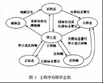
The program of the system adopts the front and background structure. The foreground is an interrupt level, and the background is a task level. The task level consists of an infinite loop and a LIN communication service program. The infinite loop contains a finite state machine and a 10ms service program. The finite state machine is shown in Figure 3. The system powers on and enters an infinite loop after completing the initialization task. Once the SCI reception interrupt occurs, the interrupt service routine judges whether the received synchronous interval field. If it is a synchronous interval field, the program does not return to the infinite loop when exiting the interrupt service, but enters the LIN communication service program to receive and process the message frame. After the communication service is completed, the program returns to the infinite loop again. According to the received message frame, the finite state machine switches to the corresponding state. In order to protect the motor, the transition between the forward and reverse states in the figure is forced to undergo an intermediate stop state transition. When an overcurrent or low voltage error occurs, the controller enters an error state, it turns off all PWM outputs, and records the error code. After the controller receives the sleep frame of the bus, it enters the sleep state, and the wake-up signal of the bus will reactivate the controller. In the forward or reverse state, the 10ms service program in the dead loop is executed every 10ms to complete tasks such as motor speed calculation, PI control algorithm, and battery voltage reading.
4.2 Customization of LIN communication message frame
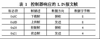
The LIN bus is a master-slave communication mode, and the customization of the message frame is carried out during the overall design of the LIN network software. The brushless DC motor controller in this paper is a slave node on the bus, and its response message frame is shown in Table 1. The flag "0x3C" is a download command frame, which is used by the master node to broadcast commands and data to all slave nodes. The first data byte with "00" is a sleep frame. The flag "0x3D" is an upload command frame, which triggers a slave node (addressed by a priority download frame) to upload data to the host. The flag "0x20" is a brushless motor control frame, which is used by the controller to receive the control information of the master node. The first data byte is "01" to request the motor to rotate forward, "02" to reverse, and "04" It is stop, the third and fourth data bytes are the given value of motor speed. The flag "0x21" is the motor status frame, which is used by the controller to transmit information to the master node. The first and second data bytes are the actual speed of the motor, and the third and fourth bytes represent the battery voltage.
4.3 Interrupt service routine in software
4.3.1 Timer A0, A1, A2 input capture interrupt (inputcap2ture ISR1)
When the timers A0, A1, and A2 detect that the position signal has a transition edge, the input capture interrupt inputcapture ISR1 is caused. In the interrupt program, read the current level of the three pins, and combine the value read in the previous interrupt, query the commutation table to complete the commutation.
4.3.2 Timer A3 input capture interrupt (inputcapture ISR2)
When timer A3 detects that the position signal of A2 channel has a rising edge transition, it causes input capture interrupt inputcapture ISR2. The interrupt program reads the current value of the timer A3 channel capture register, combines the value read in the previous interrupt and the overflow number of timer A, and calculates the count of the high-frequency clock pulse of timer A within a position pulse period. Used for speed calculation.
4.3.3 Timer B overflow interrupt (TIMERB ISR)
Timer B overflows and interrupts every 10ms, and the flag TImerflag is set in the interrupt program, so that the 10ms service program in the endless loop of the main program can be executed.
The interrupts of timer A3 and timer B are allowed to be turned off in the LIN communication service program, and the commutation interrupt is retained, thus ensuring the reliability of communication and the stable operation of the motor.
5 Test results
Using the designed controller, a brushless DC motor (the specifications of which are equivalent to the brushless motor for driving air conditioner blowers of passenger cars with a rated voltage of 48V and a rated power of 150W) is used as the test object.
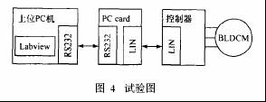
The controller in Figure 4 uses 42V / 12V dual voltage power supply. LIN Figure 4 The main node of the test chart bus is simulated by a PC. It is connected to the LIN bus through an RS232 serial port via an RS232 to LIN interface card PC card. Its LIN communication software is developed using the Labview interface environment.
The actual operation results show that: the motor can quickly start, brake, accurately and timely track the given speed of the main node, the controller runs stably and reliably, and can meet the requirements of real-time control.
6 Conclusion
The brushless DC motor controller designed by the author based on LIN bus has a simple hardware circuit structure, is compatible with the future 42V power supply system of automobiles, and has a high cost performance. In addition, because the LIN bus is an open protocol, the controller is not only suitable for the field of automotive electronics, but also for other fields such as industrial control and home appliances.
5 inch screen, square model & vertical model.
Dynamic temperature measurement Face Recognition Terminal, which performs identity recognition based on the facial feature information of the person, and uses an infrared sensor to measure and record the body temperature in real time.
Applicable to office building, community, park, campus, and other public places such as access control attendance and temperature identification management.
Time Card Punch Machine,Face Recognition Terminals,Face Recognition Terminal,Infrared Temperature Instrument
Guangzhou HangDeng Tech Co. Ltd , https://www.hangdengtech.com