With the development of science and technology, the working frequency of internal components of electronic products is constantly increasing, and the application of microwave components in electronic products is increasing. In the process of processing and component assembly of microwave components, the following problems are often encountered. Seriously affect the performance indicators or functions of microwave components, reducing the stability and service life of electronic products using these components.
1. Cavity design and processing
As the package carrier of the microwave component, the cavity has an important influence on the electromagnetic shielding, vibration shock resistance, internal signal transmission and processing of the microwave component. Many components of the microwave component are directly fixed on the inner surface of the cavity. Above, as shown in Figure 1.
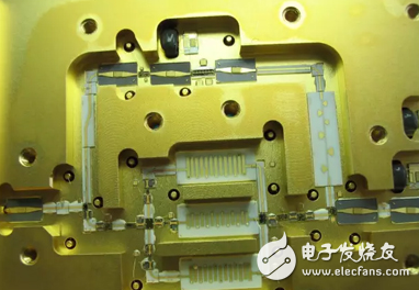
Figure 1, cavity assembly
As the internal integration of microwave components becomes higher and higher, the volume of the cavity becomes smaller and smaller, and the internal space of the cavity is utilized as much as possible. At the same time, the probability of deformation of the cavity and the loss caused by deformation are greatly increased. During the processing of parts of a microwave component or the assembly process of a component, the cavity is often deformed, which may result in the component being unusable or the internal circuit being damaged, and the component performance may be deteriorated, and the internal device may be damaged and the component may be completely ineffective. Therefore, the deformation of the cavity should be considered as a very important issue from the design, processing, assembly and other aspects. The deformation or bending or distortion of the cavity is mainly caused by the following reasons:
1.1, materials
At present, China's research and development in materials science, material production and processing, and foreign advanced technology are still no small gap, especially in the non-ferrous metal alloy materials, the gap is more obvious, the lag of research and development level and backward process equipment Domestic materials are inferior to imported materials in terms of microstructure uniformity, mechanical strength, processability and corrosion resistance. Generally, in the same processing environment, the shape of the imported material is smaller than that of the domestic material. For example, my unit originally used domestic rust-proof aluminum plate to process a cavity of a microwave component, often encountered cavity deformation can not be used, and after replacing the imported aluminum plate, the cavity shape variable is not changed when the processing equipment, the tool and the cutting parameters are not changed. It is greatly reduced, and the surface quality of the parts is also improved, which improves the yield of parts and components. Therefore, for some microwave components that are sensitive to cavity deformation, imported materials can be used.
1.2, cavity structure design
The larger the cavity size, the thinner the wall thickness is, the easier it is to deform. This is better understood. Therefore, the cavity area of ​​the cavity should be minimized during design. If necessary, the cavity wall thickness or ribs can be increased, and the inner cavity can be divided into several small areas, which can increase the strength of the cavity, reduce the deformation, and prevent it. Mutual crosstalk between circuits. At the same time, ProE, Ansys and other software can be used to simulate the thermal and mechanical aspects of the cavity model, optimize the cavity structure, and minimize the shape variables of the cavity.
1.3, processing technology
Whether the processing arrangement is reasonable or not has a considerable influence on the final qualified molding of the cavity. The machining process includes machining equipment, tools, cooling methods, and selection of process parameters such as spindle speed, feed rate, roughing and finishing allowance, as well as reasonable and necessary process arrangements, such as for some easily deformable After the rough machining removes most of the cutting allowance, the cavity inserts the aging process to eliminate the stress generated during the roughing process, and then performs precision machining to reduce the shape of the cavity. Table 1 is a method for de-stressing aging treatment of commonly used materials for cavities.
Table 1
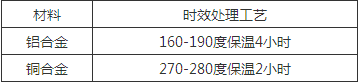
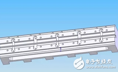
Figure 2, transmission line cavity
The different results obtained by the parts shown in Fig. 2 according to whether or not the aging treatment process is added during the processing are shown in Table 2.
Table 2
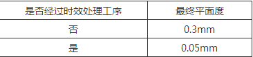
(The external dimensions of the parts are 100mmX20mmX20mm, the material is lead brass, and the processing environment is the same except for the addition of heat treatment.)
2, microstrip assembly
Among the higher frequency microwave components, the use of microstrips is quite extensive, and for such microwave components, the microstrip peeling or cracking is the most common problem, and the microstrip peeling and breaking are usually caused by the following reasons. Caused:
1) The deformation of the cavity is bent or twisted.
2) The substrate used for the cavity is inconsistent with the thermal expansion coefficient of the material used for the microstrip substrate.
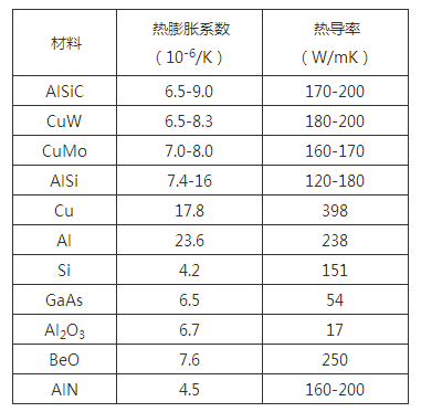
Commonly used materials for making microstrips are ceramic sheets, gemstone sheets and microwave composite dielectric sheets. The thermal expansion coefficients of these materials are inconsistent with the thermal expansion coefficients of the chambers they are filled in, and even vary greatly. Table 3 shows the thermal expansion of some commonly used materials. coefficient. In this way, when the component is subjected to high and low temperature storage or temperature shock, the absolute amount of expansion and contraction of the two components is too large, and a stress is generated between the microstrip and the cavity, and if the stress is too large, the microscopic force may cause micro The strip is peeled off or broken, as shown in Figure 3.
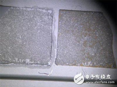
Figure 3. Microstrip cracking and shedding
table 3
To avoid this problem, you can use the following methods:
a. A pad made of a metal material (such as Kovar) similar in thermal expansion coefficient to the microstrip film is added as a transition layer between the cavity and the microstrip to buffer the stress caused by thermal expansion, as shown in FIG. .
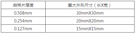
b. The size of the microstrip should be as small as possible. The larger the microstrip, the larger the absolute thermal expansion caused by the temperature difference, and the microstrip will be easily detached or broken. Therefore, the outer dimensions of the microstrip should be as large as possible. Small, Table 4 lists the recommended maximum dimensions for several different thickness microstrips for reference.
Table 4
For larger microstrip circuits, multiple microstrip splicing may be used without affecting the performance index, or a flexible material such as a microwave composite dielectric plate may be used as a substrate for making the microstrip film, thereby avoiding the film. Falling off or chipping, reducing assembly difficulty and improving production efficiency.
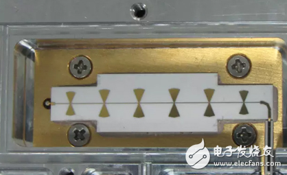
Figure 4, add pad
c. Use a flexible tablet to compress the microstrip to secure it, as shown in Figure 5.
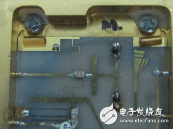
Figure 5, elastic press
3, waveguide joint surface
The ideal waveguide cavity is a completely enclosed metal cavity, but due to processing limitations or component assembly requirements, some waveguide cavity structures are divided into two parts and then assembled together with a combination of screws. However, this will introduce a new problem: due to the processing error and the deformation of the structural member, after the combination of the two parts, the bonding surface can not be in good contact, resulting in poor electrical performance of the waveguide, which cannot meet the requirements of the index.
To improve the electrical contact performance of the bonding surface, the following methods can be used.
1), appropriately reduce the area of ​​the joint surface.
From the processing point of view, the larger the surface, the more difficult it is to ensure the flatness. Therefore, in order to ensure a better contact of the bonding surface, the contact area of ​​the bonding surface can be appropriately reduced, as shown in FIG. Thus, under the same preload force applied by the screw, the force per unit area of ​​the joint surface is greater, and the contact resistance of the two joint faces can be effectively reduced.
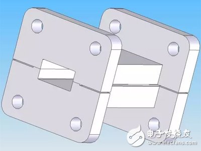
Figure 6, waveguide cavity combination
2) Add a flexible conductive material between the two bonding faces
Applying conductive adhesive or solder paste between the two bonding surfaces, or sandwiching a soft metal, such as a flexible conductive material such as indium, gold foil or copper foil, can effectively fill the gap between the bonding surfaces to reduce the contact resistance, thereby improving The electrical properties of the waveguide transmission cavity.
3), the surface of the waveguide transmission cavity is coated
The material of the waveguide transmission cavity is mostly copper alloy or gold plated on the surface of the aluminum alloy. For the waveguide with higher performance requirements, the conductivity is not particularly ideal. The gold plating or silver on the surface of the waveguide cavity can effectively improve the conductivity, especially the surface silver plating. Significantly reduce the loss of signal transmission in the waveguide. However, it should be noted that the silver-plated surface has poor corrosion resistance. If it is exposed to the air for a long time, it is easily oxidized and discolored and yellowed.
4), connected by soldering
The welding method is used to combine the flange with the waveguide or the separately processed waveguide cavity, which can also improve the electrical contact performance of the bonding surface, but this method has higher requirements on the welding process level, especially to solve the welding. How to position each part and how to reduce the deformation caused by the high temperature during welding.
This paper discusses some common problems in parts processing and component assembly and debugging of microwave components, and gives solutions. After actual production verification, these methods can effectively improve the performance index and reliability of microwave components, thereby improving the overall indicators of electronic products. And stability.
The Stainless Steel Decorative Parts including all the Stainless Steel Parts which for decorative use, like stainless pipe cover, Stainless Steel Tube end cap, staineless steel connecting joint, stainless steel elbow., etc
Stainless Steel Decorative Parts
Steel Pipe Cap,Stainless Steel Lid,Stainless Steel Cover,Stainless Steel Square Connector
Foshan Dinghan Electrical Technology Co., Ltd , https://www.dinghanelectrical.com