As electronic devices become more self-aware, the need for voltage scaling is also increasing. I am not talking about artificial intelligence, such as Hal in "2001: Space Odyssey." I mean electronic devices with more self-tests, which require reading a wide range of voltages.
Scaling the input voltage is not always as easy (or complicated) as the first time. In this article, I will show you how to solve this challenge in recent signal chain designs that need to shrink the +/- 10 V signal to the 0 to 2.5 V range to match all other signals to the analog-to-digital converter (ADC). The transfer function to achieve this goal is linear: VOUT = VIN / 8 + 1.25V.
Solution 1:
My first thought was to use a non-inverting op amp (op amp) circuit. After some fast arithmetic, I determined the circuit, as shown in Figure 1, requiring a 1.43V bias supply with a feedback/ground resistance ratio of -7/8.
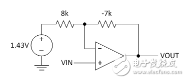
Figure 1: Solution 1 simulation is good, but impossible
The gain of the non-inverting amplifier is (1 + RF / RG). If the gain is +1/8, the resistance ratio is negative. I can't buy a -7k resistor, so this is a big problem. The input common-mode range of my op amp needs to be as low as -10V; this is also a problem because I don't have a negative supply available. Obviously, in this case, the non-inverting op amp circuit is not compatible, but it does work when the required voltage gain is greater than one.
Solution 2:
The five-resistor op amp circuit shown in Figure 2 is a differential amplifier with its inverting input to ground and a noninverting input of 1.25V. The gain is set to 1/8. The input common-mode range is 0V to 2.22V, so a single-supply op amp can be used.
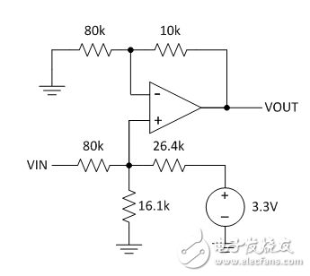
Figure 2: Solution 2 is useful, but is there a better solution?
Solution 3:
I don't need an operational amplifier to attenuate the signal. I can use the three resistors - A, B and C - and voltage source V to perform the required scaling tasks. See Figure 3.
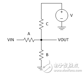
Figure 3: This simple solution uses only three resistors and an existing power supply
In my example, the gain is 1/8 and the offset is 1.25V. I will use the letters G and Z to represent the gain and offset (the output of the zero input); therefore, G = 1/8 and Z = 1.25V. My power supply voltage V is 3.3V.
So what is the best way to solve the values ​​(or ratios) of resistors A, B and C? I can calculate G and Z using Equations 1 and 2 using the resistor divider rule VOUT = VIN * RI /(RG + RI):
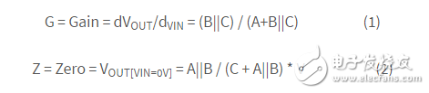
The || symbol means "parallel"; for example, x || y is x*y/(x+y) or 1/(1/x+1/y).
A manual pulse generator (MPG) is a device normally associated with computer numerically controlled machinery or other devices involved in positioning. It usually consists of a rotating knob that generates electrical pulses that are sent to an equipment controller. The controller will then move the piece of equipment a predetermined distance for each pulse.
The CNC handheld controller MPG Pendant with x1, x10, x100 selectable. It is equipped with our popular machined MPG unit, 4,5,6 axis and scale selector, emergency stop and reset button.
Manual Pulse Generator,Handwheel MPG CNC,Electric Pulse Generator,Signal Pulse Generator
Jilin Lander Intelligent Technology Co., Ltd , https://www.jilinlandertech.com