Abstract: The digital potentiometer is a commonly used device. This article describes how to use the digital potentiometer to build a low-pass filter with adjustable bandwidth.
A simple low-pass filter Figure 1 shows the audio low-pass filter formed with the DS3903. The circuit design uses a single power supply, with a power supply voltage range of 2.7V to 5.5V. Contains first-level pre-attenuation and can handle 5.0VP-P (1.77VRMS) input when powered by 5.0V. In order to produce a two-pole (the poles are at the same frequency) low-pass filter (attenuated by 12dB every tenth octave), the capacitor C3 must be more than twice the C2, the variable resistors POT0 and POT1 are set at the same value, and the cutoff frequency The calculation formula of fC) is as follows:

Where RPOT is the corresponding resistance value set by the variable resistors POT0 and POT2.
Figure 1. Audio low-pass filter with DS3903
The input part of the circuit (C1, U1-POT1, U2A, R1 and R2) is a volume control circuit, which is also used to bias the DC of the audio signal to VCC / 2 so that the signal can pass without being clamped Digital potentiometer and op amp. Under any power supply, the circuit can handle the maximum signal swing, so this design can work well at 2.7V to 5.5V VCC. The output DC level is maintained at VCC / 2, unless the circuit is operating outside the normal output, the level is shifted to a different operating point.
For applications where the operating range has been limited, the input stage circuit can be removed and connected to the filter using direct coupling. After removing the input circuit, the output signal is only the signal filtered by a two-pole filter with a cut-off frequency of fC, and the DC component of the input signal will be bypassed directly to the output.
Change the capacitance or select a digital potentiometer with different end-to-end resistance. The cut-off frequency of this circuit can be set to 500kHz.
The digital resistance model used to calculate RPOT is shown in Figure 2. For the specified position, the corresponding switch will be closed and the switches at other positions will be open. For each unit position of the potentiometer, the resistance will increase by 1 LSB (for DS3903, 10kΩ / 128 = 78Ω), except for the highest tap position, which is a parallel combination of potentiometer resistance, which will cause nonlinearity. RPOT can be calculated by the following formula:

Where: RLSB is the end-to-end resistance in the electrical parameter table of the data sheet divided by the number of taps (a). RW is the wiper resistance in the electrical parameter table of the data sheet. n is the programming position of the potentiometer. a is the total number of taps of the digital potentiometer. Figure 3 shows the relationship between the RPOT resistance value of the DS3903 10kΩ potentiometer and the position of the tap. The figure assumes an end-to-end resistance of 10kΩ and a minimum sliding-end resistance of 500Ω. These two parameters will have a significant impact on the filtering characteristics, but the main impact is the minimum and maximum values ​​of the cut-off frequency, the actual cut-off frequency can be adjusted between the minimum and maximum values, select the appropriate capacitor value can be cut-off frequency Set the required frequency within the adjustable range.
Figure 2. Resistance model of a digital potentiometer
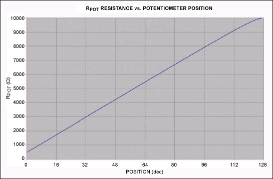
image 3.
Using the Audio Precision® test equipment to test the circuit in Figure 1, you can get the attenuation characteristics and THD + N performance shown in Figures 4 to 6.
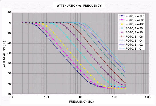
Figure 4.
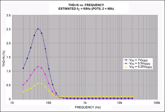
Figure 5.
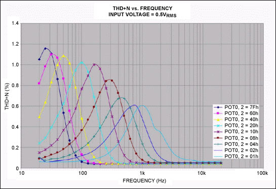
Image 6.
Digital Potentiometer Design Considerations Several factors need to be considered when selecting a digital potentiometer for a filter circuit.
The maximum limit for using a digital potentiometer is the voltage at the end of the potentiometer. Usually this voltage must be maintained between VCC and GND to avoid the audio signal clamped by the diode inside the ESD structure. When VCC is within the specified range (2.7V to 5.5V), the DS3903's ESD structure allows the input signal to be between 6V and GND. This feature is very flexible for applications requiring an input signal greater than VCC. However, the 6VP-P signal is not processed in the circuit shown in Figure 1, because the signal will be clamped when the op amp power supply is below 6V. If the op amp can be powered by a higher voltage, you can use the DS3903's large signal processing function.
The change form (linear or logarithmic) of the potentiometer tap determines the linear adjustment or logarithmic adjustment form of the circuit cutoff frequency. For the filter circuit in the audio range shown in Fig. 1, to ensure that as many cut-off frequency settings as possible between 40 Hz and 800 Hz, a linear potentiometer is more appropriate.
The resolution of the potentiometer (such as 128 or 256 taps) determines the adjustment accuracy of the cutoff frequency. The more taps, the higher the adjustment accuracy of the cutoff frequency. For audio applications, it is unlikely to use potentiometers above 64 or 128 taps to set the cut-off frequency of the low-pass filter. For broadband applications, more potentiometer taps may be required.
Some digital potentiometers use non-volatile storage to maintain the tap position when there is no power supply. This feature can be used to save the calibrated filter position, and no longer adjust the filter settings at power-up. Volatile potentiometers always start from a preset position, and the circuit will remain in the default position until it is modified.
The end-to-end resistance and sliding resistance of the digital potentiometer have a wide tolerance. The two resistors (POT0 and POT2) in the circuit shown in Figure 1 remain the same because these two resistors are fabricated on the same silicon chip. The actual resistance of potentiometers varies greatly, usually the end-to-end resistance varies by ± 20%, but their relative values ​​remain basically stable.
In addition, the digital potentiometer also has a certain parasitic capacitance, which will limit the maximum cutoff frequency. When the cutoff frequency is greater than 500kHz, it is not recommended to use a 10kΩ digital potentiometer, nor is it recommended to use a 50kΩ digital potentiometer for designs above 100kHz or a 100kΩ digital potentiometer for designs above 50kHz. For audio applications, the selected potentiometer can provide sufficient bandwidth, but for broadband applications, this factor must be carefully considered.
Op amp selection The main design considerations for this circuit for operational amplifiers are minimum stable gain and input and output voltage swings. The input stage receives the signal and biases it at the VCC / 2 DC level. The filter itself is a unity gain amplifier. To ensure reliable operation, the amplifier must be unity-gain stable; in addition, an operational amplifier with rail-to-rail input and output must be selected to handle input signals close to the circuit supply voltage.
Conclusion The digital potentiometer can be used to construct a numerically controlled low-pass filter. The two-pole filter in this article can provide good performance in audio applications. Selecting different capacitors and potentiometer values ​​can adjust the cutoff frequency of the filter, up to 500kHz .
Where RPOT is the corresponding resistance value set by the variable resistors POT0 and POT2.
Figure 1. Audio low-pass filter with DS3903
The input part of the circuit (C1, U1-POT1, U2A, R1 and R2) is a volume control circuit, which is also used to bias the DC of the audio signal to VCC / 2 so that the signal can pass without being clamped Digital potentiometer and op amp. Under any power supply, the circuit can handle the maximum signal swing, so this design can work well at 2.7V to 5.5V VCC. The output DC level is maintained at VCC / 2, unless the circuit is operating outside the normal output, the level is shifted to a different operating point.
For applications where the operating range has been limited, the input stage circuit can be removed and connected to the filter using direct coupling. After removing the input circuit, the output signal is only the signal filtered by a two-pole filter with a cut-off frequency of fC, and the DC component of the input signal will be bypassed directly to the output.
Change the capacitance or select a digital potentiometer with different end-to-end resistance. The cut-off frequency of this circuit can be set to 500kHz.
The digital resistance model used to calculate RPOT is shown in Figure 2. For the specified position, the corresponding switch will be closed and the switches at other positions will be open. For each unit position of the potentiometer, the resistance will increase by 1 LSB (for DS3903, 10kΩ / 128 = 78Ω), except for the highest tap position, which is a parallel combination of potentiometer resistance, which will cause nonlinearity. RPOT can be calculated by the following formula:
Where: RLSB is the end-to-end resistance in the electrical parameter table of the data sheet divided by the number of taps (a). RW is the wiper resistance in the electrical parameter table of the data sheet. n is the programming position of the potentiometer. a is the total number of taps of the digital potentiometer. Figure 3 shows the relationship between the RPOT resistance value of the DS3903 10kΩ potentiometer and the position of the tap. The figure assumes an end-to-end resistance of 10kΩ and a minimum sliding-end resistance of 500Ω. These two parameters will have a significant impact on the filtering characteristics, but the main impact is the minimum and maximum values ​​of the cut-off frequency, the actual cut-off frequency can be adjusted between the minimum and maximum values, select the appropriate capacitor value can be cut-off frequency Set the required frequency within the adjustable range.
Figure 2. Resistance model of a digital potentiometer
image 3.
Using the Audio Precision® test equipment to test the circuit in Figure 1, you can get the attenuation characteristics and THD + N performance shown in Figures 4 to 6.
Figure 4.
Figure 5.
Image 6.
Digital Potentiometer Design Considerations Several factors need to be considered when selecting a digital potentiometer for a filter circuit.
The maximum limit for using a digital potentiometer is the voltage at the end of the potentiometer. Usually this voltage must be maintained between VCC and GND to avoid the audio signal clamped by the diode inside the ESD structure. When VCC is within the specified range (2.7V to 5.5V), the DS3903's ESD structure allows the input signal to be between 6V and GND. This feature is very flexible for applications requiring an input signal greater than VCC. However, the 6VP-P signal is not processed in the circuit shown in Figure 1, because the signal will be clamped when the op amp power supply is below 6V. If the op amp can be powered by a higher voltage, you can use the DS3903's large signal processing function.
The change form (linear or logarithmic) of the potentiometer tap determines the linear adjustment or logarithmic adjustment form of the circuit cutoff frequency. For the filter circuit in the audio range shown in Fig. 1, to ensure that as many cut-off frequency settings as possible between 40 Hz and 800 Hz, a linear potentiometer is more appropriate.
The resolution of the potentiometer (such as 128 or 256 taps) determines the adjustment accuracy of the cutoff frequency. The more taps, the higher the adjustment accuracy of the cutoff frequency. For audio applications, it is unlikely to use potentiometers above 64 or 128 taps to set the cut-off frequency of the low-pass filter. For broadband applications, more potentiometer taps may be required.
Some digital potentiometers use non-volatile storage to maintain the tap position when there is no power supply. This feature can be used to save the calibrated filter position, and no longer adjust the filter settings at power-up. Volatile potentiometers always start from a preset position, and the circuit will remain in the default position until it is modified.
The end-to-end resistance and sliding resistance of the digital potentiometer have a wide tolerance. The two resistors (POT0 and POT2) in the circuit shown in Figure 1 remain the same because these two resistors are fabricated on the same silicon chip. The actual resistance of potentiometers varies greatly, usually the end-to-end resistance varies by ± 20%, but their relative values ​​remain basically stable.
In addition, the digital potentiometer also has a certain parasitic capacitance, which will limit the maximum cutoff frequency. When the cutoff frequency is greater than 500kHz, it is not recommended to use a 10kΩ digital potentiometer, nor is it recommended to use a 50kΩ digital potentiometer for designs above 100kHz or a 100kΩ digital potentiometer for designs above 50kHz. For audio applications, the selected potentiometer can provide sufficient bandwidth, but for broadband applications, this factor must be carefully considered.
Op amp selection The main design considerations for this circuit for operational amplifiers are minimum stable gain and input and output voltage swings. The input stage receives the signal and biases it at the VCC / 2 DC level. The filter itself is a unity gain amplifier. To ensure reliable operation, the amplifier must be unity-gain stable; in addition, an operational amplifier with rail-to-rail input and output must be selected to handle input signals close to the circuit supply voltage.
Conclusion The digital potentiometer can be used to construct a numerically controlled low-pass filter. The two-pole filter in this article can provide good performance in audio applications. Selecting different capacitors and potentiometer values ​​can adjust the cutoff frequency of the filter, up to 500kHz .
To guarantee process quality control, Xunda has line leakage detecting system, line laser barcode system, Range Hoods appliances testing system, and apply finished product sample test, first article inspection and other complete spot testing systems.
Stainless steel+tempered glass
760m³/h air flow
3 speed electronic switch
6 layers washable aluminum grease filters
2x2LED lamps
Kitchen Range Hoods,Slim Hoods,Recirculating Range Hood,Stainless Steel Range Hood
Xunda Science & Technology Group Co.ltd , https://www.xundatec.com