introduction
Current processors, imaging and storage systems use multiphase power solutions. These multi-phase solutions provide the response and regulation of a very high switching frequency converter while switching on a more moderate frequency. For single-channel buck converters, they also provide higher output currents than they actually are.
The advantages of multiphase power supplies come from phase interleaving, with 0 phase interleaving at uniform time intervals (for example, interleaving at 120° intervals in a three-phase interleaved converter), and its own single phase inherent output pattern The wave is reduced to an average by other phases, so that the overall output ripple is reduced. This uses a lower pulse width modulation switching frequency to achieve the goal of a given output ripple design while increasing efficiency by reducing switching losses.
Managing multiphase power systems has its own unique problems, including light load efficiency and phase shedding of system redundancy, and phase current balance of system life. Implementing these features in a traditional analog power supply can be difficult, but using a digital controller makes these tasks very easy.
solution
This system consists of up to six interleaved synchronous buck converters, each controlled by a single microprocessor, as shown in Figure 1.
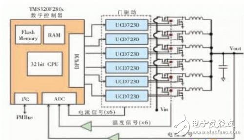
Figure 1 CNC multi-phase interleaved synchronous buck
TI's 32-bit TMS320F2806 Digital Signal Controller (DSC) operates at 100 MHz and targets power applications. In this example, it implements voltage mode control in software that uses a single-channel 2-pole 2-zero digital compensator that samples at the PWM switching frequency. The resulting duty cycle value will be passed to each buck phase (except for duty cycle adjustments made to achieve phase balance). System output voltage feedback is obtained by using an on-chip 12-bit analog-to-digital converter (ADC). The MOSFET temperature is available throughout the ADC for monitoring purposes, and the on-chip inter-integrated circuit (I2C) port provides the PMBus? Communication support. A UCD7230 gate driver has been specifically designed for synchronous buck applications to provide TI TrueDrive? The output architecture's dual 4-A MOSFET driver, periodic current limit, and a built-in low offset, high gain, differential current sense amplifier.
Phase and phase enhancement
Phase cut provides a way to increase power efficiency and reliability. Dynamically reducing the number of operating phases under light load conditions usually results in increased efficiency. When the load demand increases, a phase cut can be reactivated. Similarly, by rebalancing the interleaving between the remaining phases, cutting out a failed phase or a phase running outside the boundary state helps maintain system performance. In applications that require extreme reliability, an alternate phase can be brought online to replace the failed phase, which is the N+1 redundancy design. Regardless of the reason for resecting one phase, the stagger angle of the remaining phase (or phase added in the N+1 redundancy design) should be readjusted to maintain optimum performance. For example, cutting a phase from a three-phase 120° interleaved converter should separate the two phases by 180°.
The PWM components of the TMS320F2806 controller support software synchronization and phase control. Each PWM output has a phase synchronization register that offsets its count value from the count value of the first PWM output. This allows the phase angles of all interleaved buck phases to be statically configured not only during system initialization, but also dynamically during system operation.
Figure 2a shows an oscilloscope screen acquisition of a three-phase interleaved buck converter with a 120° interleaved (condition: 10V input, 2V output, 3A load, and 300 kHz PWM switch) PWM structure. Oscilloscope channels 1 through 3 show a single phase voltage, while channel 4 shows an interleaved output voltage (all oscilloscope channels are AC coupled). With all three phases in operation, the output ripple is 4.9 mV (0.25% of the output voltage). Without adjusting the angles of the two remaining phases (see Figure 2b), cutting the phase 2 causes the output ripple to increase by 86%, which is 9.1 mV. To obtain a 180° interlace (see Figure 2c), the two remaining phases After software adjustment, the ripple is reduced to 7.9 mV. While still larger than the initial value (because a two-phase system cannot obtain low ripple like a three-phase system), its residual phase angle is not adjusted. Increased by 13%.
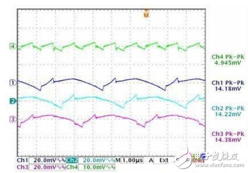
Figure 2a Three-phase interleaved synchronous buck output
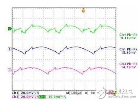
Figure 2b cuts phase 2 at 120° interleaving, leaving phase 1 and phase 3
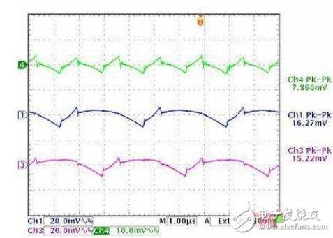
Figure 2c adjusts phase 1 and phase 3 to achieve 180° interleaving
Phase current balance
In order to optimize the reliability and service life of the power supply components, it is worthwhile to share the power load equally for each phase in the multiphase system. Due to the differences between the components of the power switch and the inductor, and the asymmetry of the board layout and heat dissipation, the current flowing through the phase is different. The basic balancing method involves measuring the phase current and separately adjusting the PWM duty cycle required for each phase to balance the current. The current unbalanced dynamics are very slow, so the sampling rate of the balanced loop can be low, which can be a few tens of seconds or even a few seconds. Therefore, the extra computational burden on the microprocessor can be ignored. To reduce the effects of sensor noise, the balanced loop rate current reading is oversampled and the current measurement for each phase is averaged over time. Simple Low Gain Complete Behavior The "only" control algorithm is typically used to turn off the balance loop. In each loop iteration using the average phase current as a reference, the balance can be performed on each phase. Alternatively, phase current balance can only be achieved by balancing the highest and lowest current phases measured at that time. Regardless of which method is used, all phase currents will eventually converge to the same value.
PWM accuracy is a problem that is often encountered when performing phase current balancing. Think of a 10V input as a 2V output synchronous buck converter driven by a 300 kHz PWM with a 100 MHz PWM clock. The PWM accuracy on this buck output will be 30 mV, or 1.5% equivalent to the 2V output. In general, it is better than achieving phase balance and avoiding the limit loop of the balance control loop. The duty cycle is adjusted so that the granularity will be one or even two orders of magnitude larger. The F2806 controller provides a solution to this problem and uniquely enhances the accuracy of the PWM module. This high precision PWM provides edge positioning of ~150 ps. This is equivalent to providing 0.45 mV output accuracy or 0.02% 2V output for the buck example above. This solution provides high accuracy and good phase current balancing.
in conclusion
This case introduces a digital power solution with the advantages of a multi-phase synchronous buck converter, while digitally shutting down the voltage control loop and managing the phase under different load and thermal conditions to get the most Good power performance.
LED street lights achieve ultra brightness/luminance; energy-saving over 70%. Special modular design for theLens (independent modules) and high luminous efficacy, high CRI, easy for maintenance.Intelligent and isolated power supply (NS semiconductor and Japan Rubycon capacitor), reliable and stable; automatically reduce current against overheating working temperature
Led Street Light Price List,Led Street Light Price,Led Street Lamp
Yangzhou Beyond Solar Energy Co.,Ltd. , https://www.ckbsolar.com