Compared with traditional halogen low-voltage illumination, LED illumination has many advantages: (1) the light source is more concentrated, the brightness obtained by 1 W illumination is equivalent to the brightness of a dozen-watt halogen lamp, so it is very energy-saving; (2) the life of LED lamp is lower than that of halogen The length of the lamp is generally tens of thousands or even 100,000 hours; (3) the structure of the LED is simple and the seismic performance is good; (4) the hot start time is not required, and the response speed of the light is fast; (5) the working voltage is 6~12 V. between. Based on these advantages, high-brightness LED lighting technology is increasingly becoming the development trend of automotive lighting, and can bring a good cost performance.
This article refers to the address: http://
Because the automotive lighting system requires simple control, energy saving, high efficiency and safety [1], this system mainly uses high-power LED driver XLT604 to drive LED illumination, using 8-bit single-chip PIC18F448 to output PWM pulses with different duty cycles to dynamically control Its luminous intensity, and the temperature of the system is tested using the digital Temperature Sensor DS18B20, while real-time control of the heating of the system. In addition, the system also uses a photoresistor sensor to adaptively adjust the brightness of the illumination system.
1 system hardware design
The system hardware mainly includes LED drive and dimming, brightness detection, temperature detection and other functional modules with single chip as the control center. The brightness detection and temperature detection modules are relatively simple. The system mainly designs LED drive and dimming module.
1.1 System overall structural design
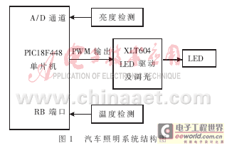
The main function of the car lighting system is to adaptively adjust the brightness of the LED according to the ambient temperature and brightness. This system uses PIC18F448 MCU as the LED control center, which uses one of the 10-bit A/D conversion channels to receive the brightness signal, the RB port receives the temperature detection signal, and outputs PWM pulses of different duty ratios to the XLT604 through the CCP module according to the brightness and temperature. The PWM driver's PWM pin adjusts the output light flux of the LED in real time, ie adjusts the brightness of the LED. The overall structure of the system is shown in Figure 1.

1.2 LED drive and dimming
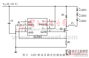
In automotive lighting systems, the LED driver circuit must be able to draw operating power from the vehicle's power bus. In an application, in order to obtain an illumination source of desired brightness, a single high power LED or a plurality of LEDs connected in series, in parallel or in series and mixed connections may be employed. Since the automotive power bus provides a nominal value of 12 V, the system uses a high-power LED driver chip XLT604 with an input voltage of 7 to 450 V. The XLT604 is a PWM high-efficiency LED driver control chip designed in BICMOS technology. It can drive an external MOSFET at a fixed frequency of 300 kHz, and its frequency can be determined by external resistor programming. The external high-brightness LED string can be controlled by constant current to maintain a constant high. Brightness enhances the reliability of the LED, and its constant current value can be determined by an external sampling resistor, which varies from a few mA to 1 A. XLT604 driving an LED brightness can be adjusted by an external control voltage is linear, may adjust the brightness of LED strings by an external low frequency PWM mode. In automotive lighting systems, it is generally only required to output a luminous flux range of 150 to 800 lm. The system uses Cree's XLamp XP-E LED to achieve 100 lm/W luminous efficiency and uses three LEDs in series [2]. The LED driver and dimming circuit are shown in Figure 2.

1.2.1 LED drive control
In Figure 2, the XLT604 uses a DC-DC buck driver with an external input voltage of 12 V and an LED string voltage of 9 V. When the GATE output high, part of the energy inductive energy storage or directly to the LED string by limiting the current system operates in a manner that the peak power tube; When the power MOSFET is turned off, the energy stored in the inductor to drive the LED is converted to Current. External current sampling resistor R2 and the power source transistor is connected in series, when the voltage value exceeds the set value R2, the power is turned off tube [2].
1.2.2 LED dimming
The XLT604 has two adjustment modes: linear adjustment and PWM adjustment. Linear adjustment dynamically controls the brightness of the LED, but reduces the efficiency of the LED and causes the color shift of the white LED to the yellow spectrum. The advantages of PWM regulation technology are obvious. When the PWM pulse is active high or low, the LED input current is maximum or 0, and its on-time is controlled by the duty cycle of the PWM pin input pulse [3]. Since the LED always operates under the same current condition, by applying a PWM signal to control the brightness of the LED, the brightness of the LED can be dynamically adjusted without changing the color. Therefore, the system adopts the PWM dimming mode. PWM signal outputted by the PWM signal to the PWM terminal of the microcontroller PIC18F448 XLT604 obtained. The PIC18F448 changes the duty cycle of the PWM pulse signal according to the temperature measured by the temperature detection module and the luminous flux signal measured by the photosensitive sensor to adjust the brightness of the LED, thereby achieving energy saving. The brightness of the LED light is proportional to the high-level time length of the PWM signal. The PWM adjustment mode can be used to dim the light from 0 to 100%, but the current higher than the set value cannot be adjusted. The PWM dimming accuracy is limited only by the narrowest pulse width of the GATE output [4].
1.3 System main control circuit design
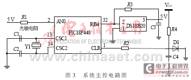
PIC18F448 MCU is the main control center of the system. It contains 4 timers, 4 I/O ports, 8 channels of 10-bit A/D converter, 2 PWM pulse outputs, SPI bus interface, etc. The resources are rich and can meet the requirements. System design requirements [1]. The system main control circuit is shown as in Fig. 3. The AN0 pin of the RA port of the PIC18F448 receives the light detection signal from the photosensor, the RB4 port receives the DS18B20 temperature detection signal, and the system outputs PWM pulses of different duty cycles to the PWM pin of the XLT604 driver according to the two variables. Thereby adjusting the output luminous flux of the LED.

The luminous flux detection is realized by a photoresistor, and a voltage of 5 V is applied to both ends. When the ambient light intensity changes, the resistance of the photoresistor changes, causing the output voltage to vary between 0 and 5 V. The temperature detection adopts the single-bus digital temperature sensor DS18B20, which has the advantages of simple structure, small size, low power consumption, user can set the warning upper and lower limit temperature, etc. The temperature range is -55 °C~+125 °C, which can be well satisfied. System temperature measurement requirements. The system uses a single bus mode to transmit temperature signals, which can greatly save the limited port resources of the single chip microcomputer, simplify the network structure of the temperature measurement network, and enhance the system's expansion capability. Because single-bus communication has a unique combination of power and signal, it uses only one port line, each chip uniquely encodes and supports networked addressing.
2 system software design
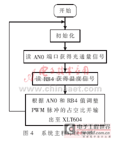
The software part of the system is relatively simple, and the main program flow chart of the system is shown in Figure 4.

After the system is powered on, the PIC18F448 is initialized first, and the detection signal and temperature signal of the luminous flux are read. Then, the duty ratio of the output PWM pulse is adjusted and sent to the PWM pin of the LXT604, and the cycle is repeated to achieve the purpose of dynamic dimming. Dynamically adjusting the PWM output pulse signal according to the temperature and the luminous flux values ​​of the duty cycle is the key element of the system software design. The duty cycle of operation of the internal registers PIC18F448 adjustable PWM pulse is output, the steps are as follows: (1) initialize CCP1 module controls the low 4-bit register is CCP1CON 11XX, TRISC.2 bits are cleared, so that in the module CCP1 In the PWM pulse output mode, the PWN pulse with a resolution of 10 bits can be output; (2) the 8-bit period register PR2 of the timer TMR2 is written to set the period of the PWM output pulse; (3) the control register T2CON of the timer TMR2 is written, Enable timer TMR2 and initialize the prescaler value of TMR2; (4) The CCP1 module contains two 8-bit registers, CCPR1H (high byte) and CCPR1L (low byte), by writing to the CCPR1L register of the CCP1CON controller. The 5-bit can get the high-level time of the PWM pulse, which can be written at any time, but the data is actually written into the CCPR1H register only when the increment count value of the timer TMR2 is equal to the value of the period register PR2. Where PWM pulse period = [(PR2) + 1] × 4 × Tosc × (TMR2 prescaler value), PWM high time = (CCPR1L: CCP1CON [5: 4]) × Tosc × (TMR2 prescaler value ), PWM output duty cycle = (CCPR1L: CCP1CON[5:4]) / (PR2 + 1) × 4.
The system adopts the design scheme of single-chip microcomputer as the control center and high-power LED illumination, which has good flexibility and expandability. The light intensity and temperature of the surrounding environment are respectively measured by the photosensitive sensor and the temperature sensor, and the brightness of the LED is dynamically adjusted according to the information, which can save energy well. The lighting system is used as the taillight illumination of the automobile. Since the LED lights up quickly, the driver of the car behind the tail can be promptly informed of the exercise state of the vehicle in front, and the occurrence of a rear-end collision accident is reduced. High-brightness LEDs have been widely used in automotive lighting systems
Sensor wires can be used in many difference sensors and probes such as NTC Thermistor, NTC temperature sensor, PTC sensor and RTD, etc. Electronic measurement, automation and control are most important in almost all industrial sectors. With more than 15 years of experience in cable manufacturing, our engineer can find variety of solutions even your needs are out of our production range, and make new designs as per your requirements.
Sensor Wire
Sensor Wire,2 Wire Sensor,Temperature Sensor Wire,3 Wire Sensor Connection
Feyvan Electronics Technology Co., Ltd. , http://www.fv-cable-assembly.com