introduction
The voltage type PWM means that the controller adjusts the output pulse width according to the feedback voltage, and the current type PWM means that the controller adjusts the output pulse width according to the feedback current. The current-mode PWM is used at the input of the pulse width comparator to directly compare the signal flowing through the output inductor current with the error amplifier output signal to adjust the duty cycle so that the peak current of the output changes in accordance with the error voltage. Because there are voltage loops and current loop double loop systems on the structure, the voltage regulation rate, load regulation rate and transient response characteristics of the switching power supply are improved, which is an ideal new PWM controller.
1 Double-loop current type PWM controller works
The dual-loop 24V power supply current-mode pulse width modulation (PWM) controller adds control of the current feedback inside the common voltage feedback PWM control loop. In addition to the function of the voltage-type PWM controller, it can also detect the switching current or inductor current. , realize double loop control of voltage and current. The circuit principle of the double-loop current type PWM controller is shown in Figure 1.
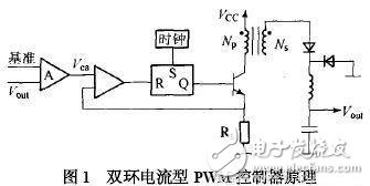
As can be seen from Figure 1, the 24V supply current type controller has two control closed loops: one is the output voltage feedback error amplifier A, which is used to generate the error voltage after comparison with the reference voltage; the other is the transformer primary (inductor) The voltage generated by the current on Rs is compared with the error voltage to produce a pulse width of the modulated pulse such that the error signal actually controls the peak inductor current.
The system works as follows: Assume that the input voltage drops, the rectified DC voltage drops, the output voltage drops due to the inductance delay, the error is delayed by the error amplifier, the Vea rises, the duty cycle changes, so that the output voltage remains unchanged, and the inductance in the current loop The peak current also decreases with the input voltage, and the slope of the inductor current di/dt decreases, causing the ramp voltage to delay reaching Vea, increasing the PWM duty cycle and adjusting the output voltage. Since the voltage and the current are controlled, the control effect is well used in practice.
2 characteristics of dual-ring current type PWM controller
a) Since the change of the input voltage Vi is immediately reflected as the change of the inductor current, the output pulse width (current control loop) can be changed in the comparator without going through the error amplifier, so that the voltage adjustment rate of the system is very good, and can reach 0.01%. /V, compared to linear shifters.
b) Due to the inherent fast response and high stability of the 24V power supply dual-loop control system, the gain of the feedback loop is high, which will not cause the contradiction between stability and gain, and the output voltage has high precision.
c) Since the peak inductor current is induced on Rs, as long as the level on Rs reaches 1V, the PWM controller is immediately turned off, forming a pulse-by-pulse current-limiting circuit, so that the peak value of the power switch tube changes in any input voltage and load transient The current is controlled within a certain range to effectively protect the main switch during overload and short circuit.
d) The error amplifier is used to control the output voltage variation caused by the load change, so that the magnitude of the voltage rise is greatly reduced when the load is reduced, and the load adjustment rate is significantly improved.
e) Since the inner loop of the system is a good controlled current amplifier, the parallel current sharing can be realized by comparing the voltage signal converted into the current sampling signal with the output signal of a common voltage error amplifier, so that the system is connected in parallel achieve.
3 double loop current type PWM controller power factor correction
Based on the above characteristics, current-mode PWM controllers are more and more widely used in practical applications. It adopts power factor correction technology, which can effectively reduce the interference of high-order harmonics to the power grid and reduce power consumption, which has great practical significance.
3.1 Power factor correction method
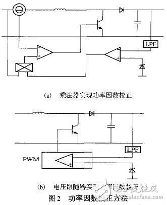
There are two main methods for power factor correction: one is to connect a common power converter on the common load side of the power grid to compensate for reactive power and harmonics; the other is to connect the load rectifier circuit and the filter capacitor. A power conversion circuit is added to correct the input current to a sine wave that is close to the grid voltage. Power factor correction can be implemented in CCM and DCM using multipliers and voltage followers. The block diagram is shown in Figure 2.
LED Street Light Heatsink, LED Flood Light Heatsink, LED Bay Light Heatsink , LED Tunnel Light Heatsink, LED High Mast Light Heatsink, housing, parts, components.
Save energy and improve road safety with connected street lighting
The complexities of transportation infrastructure mean varying types of illumination are needed to ensure traffic flows smoothly, people feel safe, and cities save on costs. Smart LED Street Lighting is a cost-effective and sustainable choice for cities today – and into the future. Led Street Lighting systems are smart and versatile, so you can manage, maintain, and monitor the entire system simply and efficiently.
LED Light Heatsink
LED Light Heatsink, LED Bay Light Heatsink, LED Tunnel Light Heatsink, LED High Mast Light Heatsink
Shenzhen Ri Yue Guang Hua Technology Co., Ltd. , https://www.ledlightinside.com