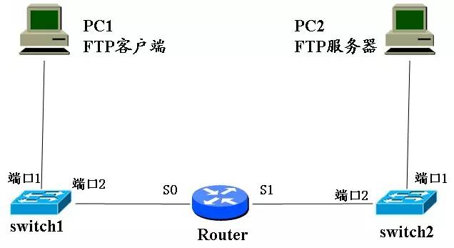
1. The FTP client sends data to the FTP server to detail its working process. The connection between the two machines is shown below:
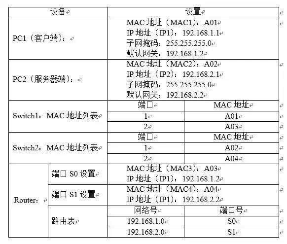
The detailed answer is as follows 1.1. Assume that the initial settings are as follows: The client FTP port number is: 32768 The server side FTP port number is: 21
1.2. The process of communicating between two computers on different network segments through TCP/IP protocol is as follows: the protocol is horizontal and the service is vertical.
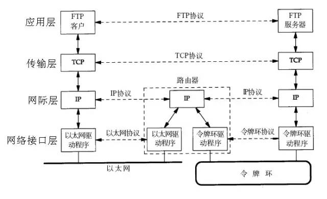
The physical layer refers to the way in which electrical signals are transmitted, and the transparent transmission bit stream. The link layer transmits data in units of frames without errors on the lines between two adjacent nodes. The network layer is responsible for providing communication to different hosts on the packet switched network. The unit of data transmission is a packet or a packet. The transport layer is responsible for communication between two processes in the host. The unit of data transmission is the segment. The network layer is responsible for point-to-point transmission (where "point" refers to the host or router), while the transport layer is responsible for end-to-end transmission (here "end" refers to Source host and destination host).
1.3, the packaging process of the data packet
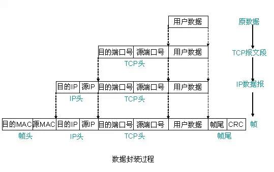
Different protocol layers have different names for data packets. The transport layer is called a segment, the network layer is called a datagram, and the link layer is called a frame. After the data is encapsulated into frames, it is sent to the transmission medium. After reaching the destination host, each layer protocol strips the corresponding headers, and finally the application layer data is handed over to the application for processing. Two computers are on different network segments, so data passes through one or more routers from one computer to another. 1.4. Working Process (1) On the PC1 client, the original data is encapsulated into a frame and then sent to port 1 of Switch 1 through a physical link. The resulting frame is:
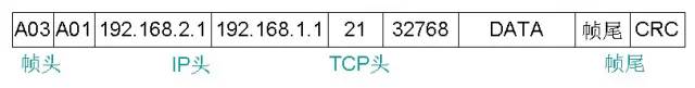
Note: How does the sender know if the destination station is in the same network segment as itself? Each IP address has a network prefix. The sender only extracts the network prefix in the destination IP address and compares it with its own network prefix. If it matches, it means that the datagram can be sent directly. In other words, compare the network numbers of the two are the same. In this question, PC1 and PC2 are in two network segments. (2) After receiving the data and verifying the data frame, Switch1 checks the destination MAC address and knows that the data is to be sent to PC2. Therefore, Switch1 stores and forwards the data frame to view the MAC address list. 2 Forward the data to the S0 port of the router. (3) After receiving the data, the Router first checks the data, then analyzes the IP datagram, re-encapsulates the data, and after viewing the routing table, sends the data out from the S1 port, and obtains a new data frame. as follows:
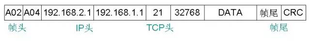
Note: The destination IP address and source IP address will not be changed. The MAC address is changed. The router will change the remote source MAC address to the next hop MAC address and then send it out. (4) Switch2 receives the Router and sends it to it. After the data is sent, it is directly stored and forwarded after verification. After viewing its own MAC address list, it sends the data frame from port 1 to the PC2 server. (5) After receiving the data, the PC2 server first performs verification, and then splits to obtain a TCP segment, thereby knowing that the destination port number is 21, and then delivering the data to the corresponding FTP application process for processing.
Second, the following problems will occur in the transmission of data, how to solve it? 1. For the data link layer, the transmitted data will be wrong or lost, and there are also different transmission speeds at both ends. How to solve these problems? A: First, we assume that host A sends data to host B. (1) Error control error control methods fall into two categories, one is to automatically request retransmission of ARQ, and the other is forward error correction FEC, also known as forward error correction code. (Forward Error Correction referred to as FEC). In the ARQ mode, when the receiving end finds an error, it tries to notify the transmitting end to resend until the correct codeword is received, and the ARQ mode only uses the error detecting code. In the FEC mode, the receiving end can not only find an error, but also can determine the location where the binary symbol is in error, thereby correcting it, and the FEC method must use an error correcting code. Commonly used error correction codes include parity check code, cyclic redundancy code, and Hamming code. For example, CRC is added to the data frame, so that host B can check whether the received data has an error. If there is an error, host B A Denial Frame NAK may be sent to Host A to indicate that Host A should retransmit the data frame in which the error occurred. (2) The lost solution times out retransmission. If host A sends the data to host B, if it has not received any acknowledgement frame ACK from host B after the retransmission time set by the timeout timer, host A retransmits the previously transmitted data frame. . (3) Flow Control 1 Assuming that the data transmitted by Host A to Host B is error-free, the simplest flow control method is: the sender temporarily stops every time a frame of data is sent, and the receiver receives the data frame. Delivered to the host, and then send a message to the sender, indicating that the received task has been completed, then the sender then sends the next data frame. In this case, the size of the receiving buffer of the receiver can be as long as the next data frame can be loaded. 2 Sliding window: Set the sending window and receiving window in the sending end and receiving end respectively to send the flow control to the sending end. The size of the sending window is WT, which means that the sending end is the most. How many data frames can be sent. Each time a confirmation of a frame is received, the send window slides forward one position. It can also be seen that in the first flow control method, WT=1. In order to control which data can be received and which data can be received when the receiving window is set at the receiving end, the receiving end allows the data frame to be received only when the received serial number of the received data frame falls within the receiving window. Each time a frame with the correct serial number is received, the receiving window slides forward one position.
2, IP datagram has its length, and in the data transmission process, some intermediate devices also have an associated setting MTU (maximum transmission unit), if it is assumed that the length of the IP datagram is 5000 bytes, and the MTU setting is 1500 words. Festival, then what should I do? A: The solution is to fragment and reorganize IP datagrams. The detailed process is as follows: 2.1, IP v4 datagram format An IP v4 datagram consists of two parts: the header and the data, wherein the data includes data that the upper layer needs to transmit, and the header is the control information added to correctly transmit the higher layer data. The first part of the header is a fixed length of 20 bytes, which must be available for all IP datagrams. Behind the fixed part of the header are some optional fields whose length is variable. The figure below shows the format of the IPv4 datagram.
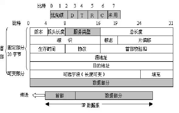
IP datagram format
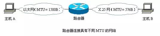
2.2. MTU values ​​of different data link layer protocols

A router may connect to different MTU networks, as shown below
2.3. When the IP datagram is fragmented, the corresponding IP header is added before each fragment to form a new IP datagram, except for some fragment control fields (such as flags and offsets). The header of the fragment is basically the same as the header of the original IP datagram. The three fields of identifier, flag, and offset are used in the IP header: identifier: 16 bits, which identifies the datagram. When the length of the datagram exceeds the maximum transmission unit (MTU) of the network, it must be split and an identifier needs to be provided for the fragment. All segments belonging to the same datagram are given the same identification value. Flag: 3 bits, indicating whether the datagram can be segmented. Currently only the first two bits make sense. The lowest bit in the flag field is MF (More Fragment). MF=1 means that the datagram of "there is still fragmentation" is followed. MF=0 table This is the last of several datagrams. One of the middle of the flag field is marked as DF (Don't Fragment). Fragmentation is only allowed when DF=0. Slice offset: 13 bits, if there is a segment, to indicate the relative position of the segment in the datagram, that is, where the slice starts relative to the starting point of the user data field. The slice offset is in 8-byte offset units, that is, the length of each slice must be an integer multiple of 8 bytes (64 Bit).
2.4. IP Datagram Reassembly The process of reassembling all the received fragments on the final destination host is the IP datagram reassembly. At this time, each segment of the IP datagram is reassembled into a complete original datagram according to the identifier, flag, offset, and the like of the datagram.
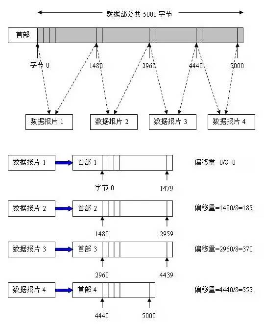
2.5 Detailed explanation of the problem The data part of the datagram is 5000 bytes long (using a fixed header), and a datagram with a fragment length of no more than 1500 bytes is required. Since the fixed header length is 20 bytes, the length of each datagram cannot exceed 1480 bytes. It is then divided into 4 datagrams, and the data portion length of the datagram is 1480 bytes, 1480 bytes, 1480 bytes, and 560 bytes, respectively. The original datagram header is copied as the header of each datagram, but the value of the relevant field must be modified. The fragmentation results are shown below:
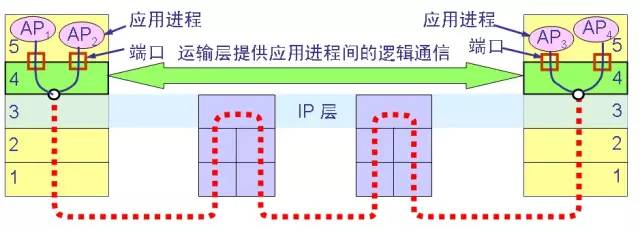
3, the application process of the two hosts, there will be errors and loss, the cache at both ends is also different, how to control the traffic? How does the application process match the port number? A: Because the transport layer provides the functionality of logical communication between application processes, the connection-oriented transport control protocol TCP guarantees full-duplex, reliable delivery of services. Specific error control and flow control are explained in detail below:
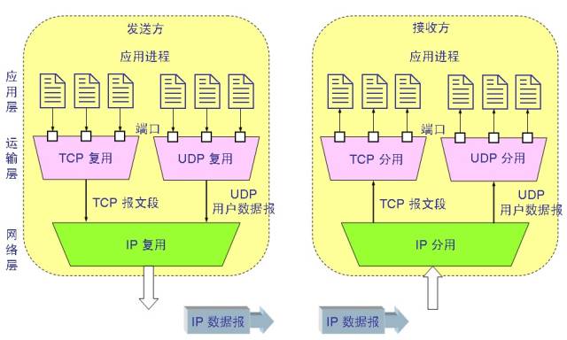
3.1. The transport layer provides logical communication for the application process that communicates with each other, as shown in the following figure:
3.2. The schematic diagram of the TCP segment is as follows:

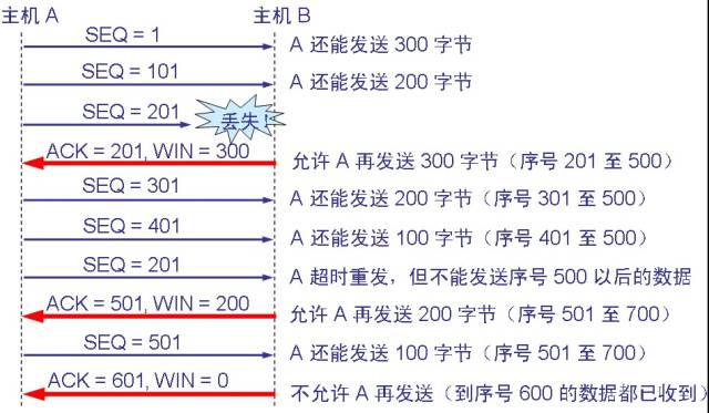
3.3. TCP Data Number and Confirmation The TCP protocol is byte oriented. TCP treats the message to be transmitted as a stream of bytes and makes each byte correspond to a sequence number. When the connection is established, both parties agree on the initial sequence number. The value of the sequence number field in the header of the message segment sent by TCP each time indicates the sequence number of the first byte of the data portion in the segment. The confirmation of TCP is to confirm the highest sequence number of the received data. The confirmation number returned by the receiving end is the highest sequence number of the received data plus one. Therefore, the confirmation number indicates the sequence number of the first data byte in the data that the receiving end expects to receive next time.
3.4, TCP flow control and congestion control (1) sliding window (for flow control) TCP uses a variable size sliding window for flow control. The unit of window size is bytes. The value written in the window field of the header of the TCP segment is the upper limit of the value of the send window currently set for the other party. The send window is agreed upon by both parties when the connection is established. However, in the process of communication, the receiving end can dynamically adjust the upper limit of the sending window of the other party (can be increased or decreased) according to the situation of its own resources.
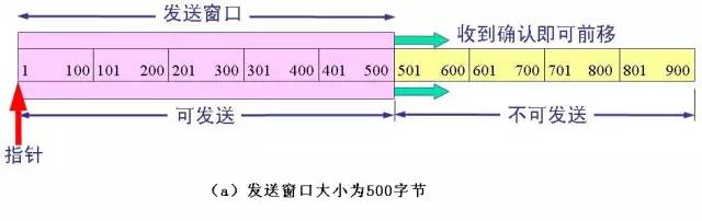
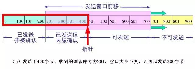
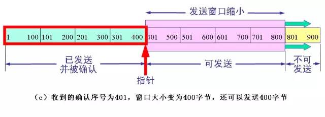
The above figure (a) shows that the sender is to send 900 bytes of data, divided into nine segments of 100 bytes long, and the transmission window is determined to be 500 bytes. As long as the sender receives the confirmation from the other party, the send window can be moved forward. Send TCP to maintain a pointer. Each time a segment is sent, the pointer moves forward by a distance of one segment. The above figure (b) shows that the sender has sent 400 bytes of data, but only received confirmation of the first 200 bytes of data, while the window size remains unchanged. The sender can now also send 300 bytes. The above figure (c) shows that the sender received the acknowledgement of the first 400 bytes of data, but the other party notified the sender to reduce the window to 400 bytes. The sender can now send up to 400 bytes of data. The window value determined by both sides of the flow control using the variable window size is 400, as shown in the following figure:
(2) Congestion Control In order to better perform congestion control, the Internet standard recommends using three techniques, slow_start, multiplicative decrease, and congestion avoidance. "Congestion avoidance" does not mean that congestion can be completely avoided. It is still impossible to completely avoid network congestion by using the above measures. "Congestion avoidance" means that the congestion window is controlled to grow linearly in the congestion avoidance phase, making the network less prone to congestion.
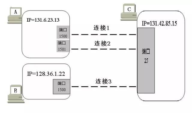
3.5, port number identification (1) port concept: port is the transport layer service access point TSAP. The role of the port is to allow the various application processes at the application layer to deliver their data down the port to the transport layer, and let the transport layer know that the data in its segment should be delivered up through the port to the corresponding process at the application layer. . In this sense, a port is a process used to mark the application layer. (2) The role of ports in the communication between processes
(3) The port number port is marked with a 16-bit port number. The port number only has a local meaning, that is, the port number is only for marking each process in the application layer of the computer. The same port number of different computers on the Internet is not connected. There are two types of port numbers: one is a well-known port, and its value is generally 0 to 1023. When a new application appears, it must be assigned a well-known port. The other type is a generic port that is used to assign to the client process requesting communication at any time. The role of the port can be represented by the following figure:
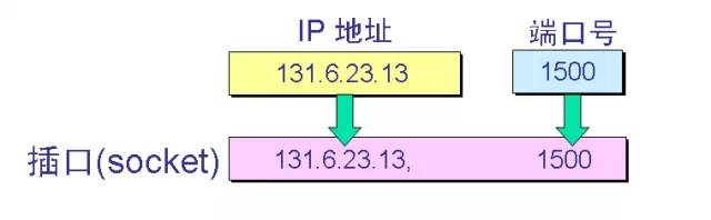
(4) Socket TCP uses "connection" (not just "port") as the most basic abstraction, and refers to the endpoint of the TCP connection as a socket, or a socket or socket. The socket includes an IP address (32 bit) and a port number (16 bit) for a total of 48 bits. The relationship between the socket and the port and IP address is:
Jasminer Machine:Jasminer X4,Jasminer X4-Q,Jasminer X4-1U,Jasminer X4-C 1U,Jasminer X4 BRICK
As a leading brand in the high-throughput server industry, JASMINER has always placed scientific and technological research and product innovation in the highest strategic position and has no upper limit on R&D investment. It is the dedication to technology research and development that enables JASMINER to take the lead in the field of energy saving technology.
At present, JASMINER is one of the world's few cutting-edge computing server brands that apply the core chip technology of "integrated storage and computing". With the chip stacking technology, JASMINER X4, the industry's leading high-throughput computing chip of integrated storage and computing, has overcome Moore's law and led the world. Thus, the energy saving, stability and reliability of the computing power server are further improved.
Based on energy saving, consumption reduction and comprehensive cost optimization, JASMINER X4 series server products have gained strong competitiveness in green environment protection, cost reduction and efficiency improvement for global customers. X4 products based on high-throughput chip architecture, with strong computing performance and excellent energy efficiency, fully meet the needs of green computing, for the development of the new generation of information technology to provide a powerful new data infrastructure guarantee.
Jasminer Machine,X4 1U Etc Miner,jasminer miner,X4 1U 520Mh Miner,jasminer x4
Shenzhen YLHM Technology Co., Ltd. , https://www.asicminer-ylhm.com