Stepper motor is an open-loop control motor that converts electrical pulse signals into angular displacement or linear displacement. It is the main actuator in modern digital program control systems and is widely used. . In the case of non-overload, the speed and stop position of the motor depend only on the frequency of the pulse signal and the number of pulses, and are not affected by the load change. When the stepper driver receives a pulse signal, it drives the stepper motor. The set direction is rotated by a fixed angle called the "step angle" whose rotation is performed step by step at a fixed angle. The angular displacement can be controlled by controlling the number of pulses to achieve the purpose of accurate positioning. At the same time, the speed and acceleration of the motor rotation can be controlled by controlling the pulse frequency, thereby achieving the purpose of speed regulation.
The stepping motor is an induction motor. Its working principle is to use electronic circuit to supply power when the DC power is changed into components. The multi-phase timing control current is used to supply the stepping motor with this current, and the stepping motor can work normally. The driver is a time-sharing power supply for the stepper motor, multi-phase timing controller.
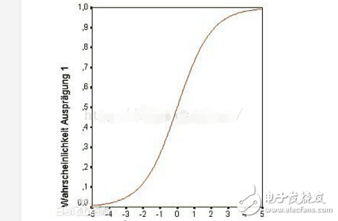
S-curve acceleration and deceleration algorithm and implementation of stepping motor Equation of the S-curve  The graph in [-5, 5] is shown below:

To apply this curve to the acceleration and deceleration of a stepper motor, the equation needs to be translated in the XY coordinate system, and the curve is pulled up and changed:

The A component is translated in the y direction, the B component is stretched in the y direction, and the ax+b component is translated and stretched in the x direction.
Accelerated process in the project: accelerate from 5600Hz to 64000Hz, using 4 subdivisions. The output of the comparison module uses a timer drive frequency of 10M, which is accelerated by 1000 points. Finally, according to the needs of the project, the curve equation used in the acceleration process is:
 .
.
Where Fcurrent is a single frequency value in length (1000) points. The starting frequency of Fmin is 5600; Fmax is the maximum frequency of 64000; -flexible*(i - num)/num is the tensile change of the S-shaped curve, where flexible represents the S-curve interval (the larger the value represents the most powerful compression, the middle ( The acceleration is larger around the x coordinate 0 point; the smaller the closer to the uniform acceleration. The ideal S curve is 4-6), i is the index in the loop calculation process, starting from 0, num is length/2 size (This can make the S curve symmetrical). In the interval i of the project [0, 1000), num = 1000/2 = 500. These parameters can be modified. The calculation interface provided is as follows.
Corresponding calculation interface code:
/* calculate the Period and Freq array value, fill the Period value into the Period register during the TImer interrupt.
*calculate the acceleraTIon procedure , a totally 1000 elements array.
* parameter fre[]: point to the array that keeps the freq value.
* period[]: point to the array that keeps the TImer period value.
* len: the procedure of acceleraTIon length.it is best thing to set the float number, some compile software maybe transfer error if set it as a int
* fre_max: maximum speed, frequency vale.
* fre_min: start minimum speed, frequency vale. mind : 10000000/65535 = 152, so fre_min can't less than 152.
* flexible: flexible value. adjust the S curves
*/
Void CalculateSModelLine(float fre[], unsigned short period[], float len, float fre_max, float fre_min, float flexible)
{
Int i=0;
Float deno ;
Float melo ;
Float delt = fre_max-fre_min;
For(; i"len; i++)
{
Melo = flexible * (i-len/2) / (len/2);
Deno = 1.0 / (1 + expf(-melo)); //expf is a library function of exponential(e)
Fre[i] = delt * deno + fre_min;
Period[i] = (unsigned short)(10000000.0 / fre[i]); // 10000000 is the timer driver frequency
}
Return ;
}
// start move motor
Void StartPWM()
{
DriverMotorFlag = TRUE;
Index = 0;
MOTOR_EN_DISABLE = ENABLE;
OpenOC4(OC_ON | OC_TIMER_MODE16 | OC_TIMER3_SRC | OC_PWM_FAULT_PIN_DISABLE, 0, 0);
// map rc13 to oc4 output
RPC13R = 11;
// 50 percent duty
OC4RS = OC_PERIOD_MIN / 2;
OpenTimer3(T3_ON | T3_PS_1_8, OC_PERIOD_MIN);
INTSetVectorPriority(INT_TIMER_3_VECTOR, INT_PRIORITY_LEVEL_6);
INTSetVectorSubPriority(INT_TIMER_3_VECTOR, INT_SUB_PRIORITY_LEVEL_1);
EnableIntT3;
}
//stop motor, hereis no deceleration
Void StopPWM()
{
DriverMotorFlag = FALSE;
Index = 0;
MOTOR_EN_DISABLE = DISENABLE;
OpenOC4(OC_OFF | OC_TIMER_MODE16 | OC_TIMER3_SRC | OC_PWM_FAULT_PIN_DISABLE, 0, 0);
// map rc13 to oc4 output
RPC13R = 0;
PORTCbits.RC13 = 0;
CloseTimer3();
DisableIntT3;
}
//change the timer Period value in the correspond timer timer rather than the other place, Or the motor will be stalled occasionally.
// At the beginning, I changed the Period value of timer3 applied to the OC module every 1ms in another timer interrupt. The structure accidentally caused the motor to stall during the acceleration process. In fact, it should be modified in the interrupt of timer3.
Static unsigned short CountForAcc = 0;
Void __ISR(_TIMER_3_VECTOR, ipl6) Timer3OutHandler(void)
{
// clear the interrupt flag, or the interrupt will not occur again.
mT3ClearIntFlag();
If(CountForAcc++ 》 2) // here can adjust the totally time of acceleration
{
CountForAcc = 0;
//if(DriverMotorFlag == TRUE && PR3 》 OC_PERIOD_MAX + SPEED_STEP)
If(DriverMotorFlag == TRUE && Index " ACC_TIMES)
{
PR3 = Period[Index++];
OC4RS = PR3 / 2;
}
}
}
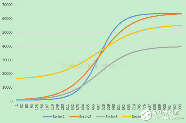
The following different acceleration curves are obtained through the CalculateSModelLine interface:
Yellow: CalculateSModelLine (Freq, Period, 1000, 56000, 16000, 4);
Orange: CalculateSModelLine (Freq, Period, 1000, 64000, 500, 8);
Blue: CalculateSModelLine (Freq, Period, 1000, 64000, 500, 15);
Gray: CalculateSModelLine (Freq, Period, 1000, 40000, 500, 5);

Finally, you can estimate the time and angular displacement of the acceleration process. Take the orange curve as an example: CalculateSModelLine (Freq, Period, 1000, 64000, 500, 8) as an example (assuming there is no if(CountForAcc++ 2) conditional constraint in the interrupt):
Time: The value of the first point of Period is 10000000/500 = 20000, and the last point is 10000000/64000=156. The average value is about 10000. The average time of timer interrupt is Tn=10000/10000000=1ms, 1000 points. The total time is 1 s. Of course, the initial acceleration frequency is shorter. For example, Fmin=16000 Hz and Fmax=64000, the acceleration process can be completed in about 40 ms.
Angular displacement: 1.8 (single step) * 1000 (steps) / 4 (segmentation) = 450°
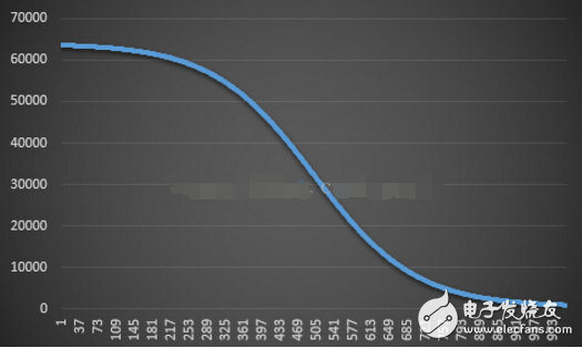
The above is the acceleration process, the same reason for deceleration, just change the equation to:

The deceleration curve can be obtained as follows:

Thermal Cutout,Capillary Type Thermostat,Freezer Used Thermostat,Adjustable Thermostat
Foshan City Jiulong Machine Co., Ltd , https://www.jlthermostat.com