As we all know, the stepper motor drive method has a full step, half step, subdivision drive. There are differences and connections between the three. At present, many drives on the market support subdivision driving methods.
It is well known that a stepper motor is a control motor that converts an electrical pulse signal into a mechanical angular displacement, often acting as an actuator in a digital control system. When the stepper driver receives a pulse signal, it drives the stepper motor to rotate a fixed angle in the set direction (this angle is called the æ© angle).
In normal motion, it has a fixed number of steps per revolution; when performing continuous stepping motion, its rotational speed maintains a strict correspondence with the frequency of the input pulse, and is not affected by voltage fluctuations and load changes. This article will lead you to understand in detail the working principle, advantages and disadvantages of stepper motor full-step drive, half-step drive, subdivision drive.
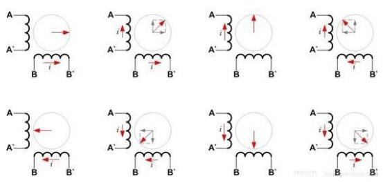
Stepper motor driveThe following figure shows the internal stator of a two-phase stepper motor. In order to make the rotor of the motor rotate continuously and smoothly, the stator must produce a continuous, average magnetic field. Because from a macro perspective, the rotor of the motor always follows the direction of the magnetic field synthesized by the stator of the motor. If the magnetic field of the stator synthesis changes too fast and the rotor does not follow, the stepper motor will be out of step.
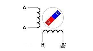
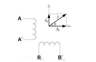
Since the rotor of the motor follows the magnetic field of the stator of the motor, the strength and direction of the stator magnetic field of the motor are determined by the stator combined current and proportional. That is, as long as the stator current of the motor is controlled, the purpose of driving the motor can be achieved. The figure below shows the current synthesis of a two-phase stepper motor. Where Ia is produced by the AA' phase and Ib is produced by the BB' phase. The current I generated by the two synthesis is the combined current of the motor stator, which can represent the magnitude and direction of the magnetic field generated by the motor stator.
Based on the background description of the above stepper motor, the three methods of stepping, half step, and subdivision of the stepping motor are the same method, except that the current divides a circle (360°) into different thicknesses.
1, the whole step drive
For the full-step drive mode, the motor is a full step. For example, for a stepper motor with a step angle of 3.6°, the whole step drive is 3.6° for each step.
The following figure is a schematic diagram of the current sequence of the motor stator in the whole step drive mode:
As can be seen from the above figure, the whole step drive only has one phase energized at a time, so the drive circuit of this drive mode can be very simple, the program code is relatively easy to implement, and the phase sequence of the motor can be obtained from the above figure:
BB'→A'A→B'B→AA'→BB'
The figure below shows the current vector segmentation of this drive:
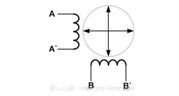
It can be seen that the current vector of the whole step driving method divides a circle into four parts.
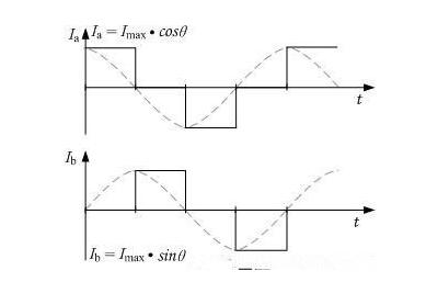
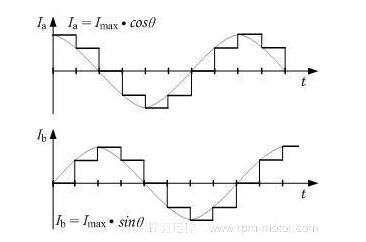
The figure below shows the current I vs T of the A and B phases of the whole step drive mode:
to sum up:
It can be seen that the disadvantage of the full-step drive is that the traced sine wave is rough. Using this method to drive the stepper motor, the motor will shake at low speed and the noise will be large. However, the advantages of this type of drive: it is relatively simple in terms of hardware or software, so that the manufacturing cost of the drive is easily controlled.
2, half step drive
For the half-step drive mode, the motor is one and a half steps. For a stepper motor with a step angle of 3.6°, the half-step drive is one step away and is 1.8° (3.6°/2).
The following figure is a schematic diagram of the current sequence of the motor stator in the half-step drive mode:
It can be seen from the above figure that the half-step driving method is relatively more complicated than the whole-step driving method. At the same time, both phases may need to be energized. If the torque required to rotate the motor is stable, it is necessary to energize when the two are energized at the same time. The current should be sin (45°) of the single-phase current, ie √2/2. Of course, the current equal to the single-phase current can be directly passed, and as a result, the torque during the rotation of the motor is not constant, but the benefit is the simplification of the drive circuit or software writing.
The following is the drive phase sequence for this type of drive:
BB'→BB' A'A→A'A→B'B A'A→ B'B→B'B AA'→AA'→ AA' BB'
If you need to reverse, just power up in the reverse direction of the above phase sequence.
When the motor is energized according to the above phase sequence, the generated current vector can divide a circle into 8 parts, as shown in the following figure:
On the one hand, the half-step drive doubles the step resolution of the motor and the motor runs more smoothly.
Contrastly, the two-phase current diagram of the half-step drive mode is shown below:
to sum up:
As seen from the above figure, the advantages of the half-step driving method: the sine wave drawn is improved compared to the full-step driving method, and the accuracy is improved. This has the advantage that the motor's step angle resolution is doubled and the motor runs relatively quietly without changing the motor.
3, subdivision driver
As shown below, you can see some kind of law:
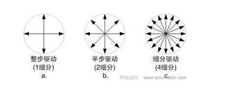
Looking at the picture above, the current vector split circle is getting denser and denser, as shown in the figure above. This is a segmentation diagram of the 4 subdivision drive. From a macroscopic point of view, the angle of the motor rotor step will decrease as the number of subdivisions increases, and the motor rotation will become more and more stable and quiet. In a sense, the whole step and half step drive are also subdivision driven, and their relationship is like the relationship between square and rectangle.
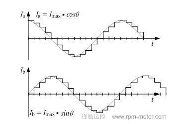
The figure above is a two-phase current diagram of the four subdivision drive mode. It can be seen from the figure that the current curve of each phase is more delicate than the current curve of the half step drive.
Current subdivision is one of the methods of subdivision driving. The implementation of constant current is commonly driven by chopping, and the given current is distributed by sine wave. The other is voltage subdivision. This method is to drive the motor coil than the voltage of the sine wave. It can realize the subdivision drive of the motor without feedback. However, due to the back EMF of the motor, the sine wave voltage cannot be driven. The sinusoidal current is generated, and the effect is not subdivided by current, but its driving circuit is relatively simple.
to sum up:
Subdivision can improve the step angle resolution of the motor. However, this is not the original intention of the subdivision drive. It is to slow down the vibration and noise of the stepper motor and make the torque output of the motor smoother. This is a bit like the relationship between optical zoom and digital zoom of a digital camera. It is best to rely on the motor itself and the mechanical structure to improve the resolution of the stepper system.
In engineering applications, the number of subdivisions of the motor may be different. At low speeds, the number of subdivisions may be increased, and when the speed is increased, the number of subdivisions may be reduced.
OSD, short for On Screen Display, is used On CRT/LCD displays to produce special glyphs or graphics On the Screen of the Display to give the user information.
In CRT/ LCD display, the working principle is to generate a complete picture control by horizontal and vertical synchronization signals. The external environment can generate image signals at appropriate points in time to generate images on the screen.
TTL (transistor-transistor Logic) is a transistor-transistor Logic in which the TTL level signal is generated by a TTL device. TTL device is a kind of digital integrated circuit. It is made by bipolar process and has the characteristics of high speed, low power consumption and many varieties.
TTL interface is an interface for data transmission in parallel mode. When using this interface, it is not necessary to use special interface circuits at the driver board end and the LCD panel end, but the TTL data signal output by the driver board main control chip is directly transmitted to the LCD panel input interface through the cable. Due to the high voltage of TTL interface signal, many connections and long transmission cables, the anti-interference ability of the circuit is relatively poor, and electromagnetic interference (EMI) is easy to occur. In practical applications, TTL interface circuits are often used to drive small size (below 15in) or low resolution LCD panels. The TTL maximum pixel clock is only 28MHz.
TTL is the only signal that can be recognized by TFT-LCD when the signal is emitted. The early digital processing chips were all TTL, that is, RGB is directly output to TFT-LCD.
Lvds Cable ,Backlight Cable,Edp Cable,Fpc Connector And Extender
TONYA DISPLAY LIMITED , https://www.tydisplay.com