1 Introduction
The traditional instrument for measuring blood pressure is a mechanical mercury sphygmomanometer, which has only appeared on the market in recent years. Compared with traditional sphygmomanometers, electronic sphygmomanometers are simple and easy to use, but their accuracy and stability are often not ideal. The design strives to be accurate and stable, and is suitable for the elderly or patients to monitor their blood pressure and clinical medical tests at any time.
Based on the research of existing products or design concepts at home and abroad, using advanced signal processing technology and intelligent control technology, the noise interference and nonlinear distortion in pulse extraction processing are eliminated as much as possible, and the accuracy and stability of blood pressure measurement are improved. Improve the automation and intelligence of measurements.
2 system hardware design
This design uses Motorola's MPX53GC silicon pressure sensor and TI's MSP430F149 microcontroller as the main components to form an electronic sphygmomanometer. The system structure is shown in Figure 1. The system consists of MCU, sensor, LCD liquid crystal display, operation panel, charge and discharge control circuit, air pump and air valve, buzzer, memory, power supply and other parts.

2.1 Microprocessor selection
The one-chip computer is the brain of the whole system. It not only monitors the system, but also performs arithmetic processing on the data. It is necessary to adjust the parameters of the hardware by judging the measurement results; the system can automatically adjust to the optimal working state, and has certain intelligence. According to the design requirements of the system, TI's MSP430F1 49 single-chip microcomputer is selected.
The MSP430 embeds the ADC12, which is a 12-bit A/D analog-to-digital converter with high speed and versatility. The ADC 12 can convert one of eight external analog signals or one of four internal voltages. The ADC12 has a general purpose sample/hold circuit that gives the user a choice of sampling timing. MSP430F149 microcontroller can meet the requirements of system design.
2.2 Sensor circuit design
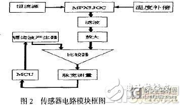
The MPX53GC is a Motorola X-type sensor that is inexpensive, linear, low-noise, responsive, and has a white-weight compensation in the case of a constant current source. The composition of the sensor circuit is shown in Figure 2. The output signal of the pressure sensor is first filtered and then amplified. At the same time, the MSP430F149 will generate a 1:10 pulse width control sawtooth generator to generate the sawtooth wave and the processed pressure signal. In comparison, the level signal is converted to a pulse width signal. The single chip MSP430F149 measures the pulse width and then converts it to systolic blood pressure (SP), diastolic blood pressure (DP), and average pressure (MP) through corresponding arithmetic processing.
2.3 Filter circuit design
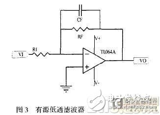
In the blood pressure measurement process, since the signal output from the sensor MPX53GC is extremely weak and mixed with high frequency noise, if the circuit design is unreasonable, the weak signal will be overwhelmed by noise. Therefore, in each stage of the amplifying circuit, there should be a corresponding noise filtering or suppression circuit. In addition, the coupling of the distributed capacitance and the distributed inductance should be eliminated as much as possible, and shielding should be performed where necessary. As shown in Figure 3, an active low-pass filter is used to effectively attenuate high frequency noise and amplify the signal appropriately. Its frequency function can be expressed as:

2.4 Charge and bleed control circuit design
Charge and discharge circuits are also an important factor affecting measurement accuracy. Therefore, how to control the inflation valve and the bleed valve to get the best measurement results is the key. In the measurement process, we use the single-chip MSP430F149 to control the charging and discharging rate, and control the action of the inflation valve and the deflation valve according to the pressure. This not only can accurately control the rate of charge and discharge, but also can well monitor the operation of the whole system. In addition, in addition, some unexpected human injuries can be avoided.
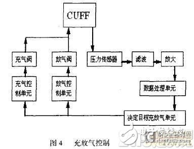
The control process is shown in Figure 4. The inflatable circuit is shown in Figure 5. During the inflation process. The aeration can be performed a little faster and the systolic and diastolic pressures can be estimated to calculate the rate of deflation. When the maximum value is reached, the inflation is stopped and the slow average deflation begins. During the deflation process, PWM pulse width modulation is used for control, and the pressure of the blood pressure cuff CUFF is constantly observed to maintain a uniform deflation. Finally, when the pressure is less than 20mmHg, immediately open the bleed valve.

2.5 LCD liquid crystal display module design
The system uses the LCD driver HT1621, which is a 128 (32 & TImes; 4) segment LCD driver that can drive multiple LCD screens. It interfaces with the microcontroller as shown in Figure 6. The interface requires only four wires. The line is used to initialize the serial interface circuit and terminate communication between the MSP430F149 and the HT1621. Data 渎/write and command writes are transmitted through the data line. The RD reads the signal and the data in the RAM is sent to the data line on the falling edge of the RD signal, causing the MSP430F 149 to read the correct data between the rising edge and the next falling edge of the signal.
A WR is a write signal, and the data, address, and command on the data line can be written to the HT1621 on the rising edge of the WR signal. IRQ is an optional control.
2.6 power module design
The system power supply is powered by two 1.BY batteries, and the XC6382 chip is boosted to 3.5V to directly supply power to the system.
3 software design
The software part is the core of the effective work of the whole system. The system can only work normally if the software and hardware are organically combined.
3.1 Acquisition and Control Program Module
It completes the collection of data (pressure sensor signal, button signal, etc.), control charging and deflation and other functions. The program flow is shown in Figure 7.
3.2 Data Processing and Display Module
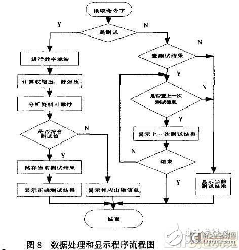
The data processing and display module performs digital filtering of the pressure sensor data to calculate systolic, diastolic, mean, and pulse pulses, and then stores the corresponding data in EEPROM (24C256) and displays it on the LCD (HT1621). The program flow chart is shown in Figure 8.
4 system calibration
The measurement system needs to be calibrated, and the electronic sphygmomanometer is no exception. There is a pressure calibration program in the software system, the function of which is to help the debugger to debug. The debugging process is as follows: zero pressure on the system (ie: let the sensor communicate with the atmosphere), after a period of stability, the system automatically records the pulse width of the zero point; then prompts the debugger to give the system a pressure of 300mmHg, at which point the debugger should display The value is adjusted to 16268±100, and the system is calibrated.
5 Conclusion
Through a series of analysis, research and improvement, the system design is better to meet the requirements of our test. In the process of measurement, the subject should be kept still, otherwise it may form a false pulse signal due to the action of the subject, and may change the CP signal. To further improve accuracy and reliability, sensor linearity, PCB layout, air pump and valve selection, etc., require further research and improvement.
3 In 1 Usb Hub,Usb C Hub Vga,Type C Hub 3 In 1,USB HUBs with HDMI,docking station USB C.
Shenzhen Konchang Electronic Technology Co.,Ltd , https://www.konchang.com