Aiming at the shortcomings of traditional humanoid robots in real-time control and visual recognition of control system, S3C6410 is used as the main control chip. The humanoid robot control system with visual recognition function is designed. Good target recognition is achieved by improving and simplifying the video recognition algorithm. effect. Experiments show that the humanoid robot designed based on the control system has good real-time performance, accurate target recognition, and can quickly find the target by adjusting the motion path.
Intelligent mobile robot is a comprehensive discipline developed in recent years, involving mechanical design, sensing, artificial intelligence and many other aspects. The humanoid robot's control system is divided into three levels: the top layer is the robot's strategic planning layer, which uses various algorithms to implement the functions of each part; the middle layer runs the embedded real-time operating system of various applications; the bottom layer is the hardware. The platform obtains various types of data and information through the peripheral interface.
The autonomous robot uses the information acquired by the sensor to control the motion of the robot. According to the actual needs of martial arts robots, this paper designs the control system of the robot to realize the functions of camera image acquisition, processing and steering control.
In the strategy planning layer, because the image information has rich information and complete description of the scene, the color target positioning is mainly realized by processing the image information collected by the camera. Here, the Linux embedded operating system is adopted. Due to the limitation of the embedded system resources, the target recognition algorithm is required to operate efficiently and occupy a small memory space. The hardware platform mainly controls the steering gear to realize the motion control of the robot.
1 system control circuit and video recognition algorithm
1.1 Overall architecture of the robot
In the martial arts technical challenge, the robot collects the position information of the target. Due to the limited effective detection distance of I/O and A/D conversion, the robot uses the camera to collect image information on the site, and recognizes and locates according to the color of the target. When the target position is detected, the autonomous movement of the steering gear is controlled to move closer to the target, and the self-introduction and the hydrangea are completed. The designed robot is shown in Figure 1.
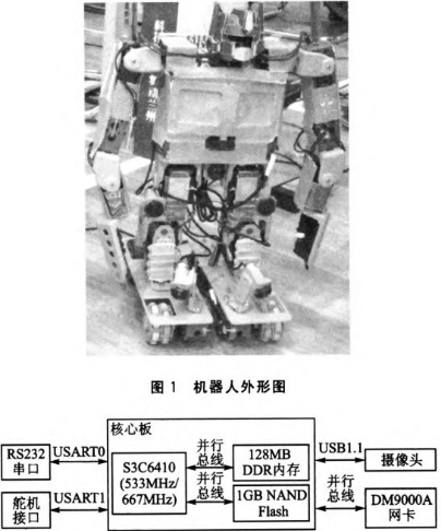
As can be seen from the figure, the robot head is connected to the main control board through a USB interface for capturing image information. The joints of the waist, legs and arms of the robot have a certain degree of freedom by using the steering gear. The steering gear used is the CDS series digital steering gear. It has an ATmega8 chip inside, and the main control board communicates with ATmega8 through the serial port, which can realize the control of the servo. In response to the above requirements, and considering the real-time nature of the system, S3C6410 is used as the main control chip. The overall block diagram of the actual control system is shown in Figure 2.
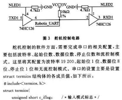
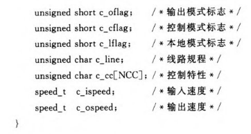
1.2 Steering gear control system design
The main control board completes the data communication with the servo through the serial port 1. The schematic diagram of the servo control circuit is shown in Figure 3.
2 image recognition algorithm
The image captured by the camera is mainly processed as follows: firstly, the data is decoded, and the RGB spatial model data is converted into an HSI space model by using the look-up table method, and then the image is binarized by the inter-class variance method, and then the connected domain is used to perform the target. Calibration, and finally denoising the image to achieve target recognition and positioning. The image processing program flow chart is shown in Figure 4.

After the color space conversion is realized, the image is binarized according to different H values. The essence of binarization is a classification problem, that is, binary pixels of 0-255 contained in an image are divided into two categories according to a certain threshold. If the threshold is set too low, the result will introduce too much background information, but too high will result in the loss of the target information. The inter-class variance method (Otsu), the maximum entropy method (KSW), and the Balanced Histogram Thresholding (BHT) are currently widely used automatic threshold calculation methods.
The inter-class variance method is used here. Its core idea is to find the optimal threshold by maximizing the variance between classes. Assuming that a certain threshold T divides the entire binary image into C0 (1, ..., T) and C1 (T, ..., 255), the probability of occurrence of the two types can be calculated by:
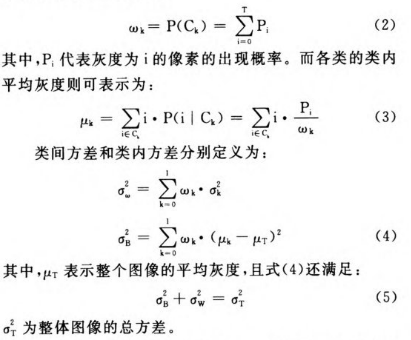
As mentioned above, the criterion for determining the optimal threshold is to maximize the variance between classes. Then by traversing each gray value and calculating the variance between the classes caused by the partition, a suitable threshold can always be found to satisfy the condition. Since the calculation of the second-order central moment of equation (4) is large, consider:
The next task is to calibrate the image. The calibration here refers to calculating the circumscribed rectangle position of the target area based on the binarized image. In the case where the target composition is relatively simple, the projection method is the most efficient method, and when there are multiple targets in the scene, the connected domain calculation is required in most cases. In topology, connectivity is defined as the presence of at least one curve between any two points in the region to connect the two. The current connected domain labeling methods fall into two main categories: scanning and contour tracking. The basic idea of ​​the scanning method is to check the value and connectivity of each pixel one by one, so as to obtain all the connectivity description information, and then calculate the final number of regions and the composition relationship according to the relationship between each point. The scan-based connectivity mark is demonstrated as follows (taking 8 connections as an example):
First, a line scan of the binary image is performed to obtain a line segment connection mark, as shown in FIG. Then check the connection between the line segment between each line and the line segment of the previous line, and change the mark.
Line 1: Line 1 creates marker A.
Line 2: Lines 2, 1 are connected, Line 2 is marked A; Line 3

3 experiment and result analysis
The control card is attached to the robot to control the movement of the robot. During the movement, the camera captures the image and the target is calibrated with a square. The red hydrangea of ​​the figure is calibrated by the above color recognition algorithm, and the result shown in Fig. 7 is obtained.
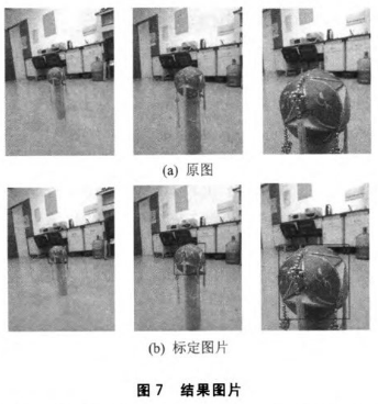
With the movement of the robot, the position of the hydrangea in the image changes, and the robot can obtain the position of the hydrangea according to the calibration result, and accurately adjust the movement according to the position to find the hydrangea. The image acquisition speed reaches 15 frames/s, and the servo control accuracy reaches 0.32°, which can successfully complete the game task.
Conclusion
In this paper, S3C6410 is used as the main control chip, and a humanoid robot control system with visual recognition function is designed. The improved color recognition algorithm uses the look-up table method, the inter-class variance method, and the connected domain to process the image, and obtains a good video recognition effect. Practice has proved that the humanoid robot made by the design scheme of the control system has good autonomous control stability and good visual recognition ability, and can complete the competition better.
Portable Battery ,Portable Power Bank,Portable Battery Pack,Portable Power Pack
Zhejiang Casnovo Materials Co., Ltd. , https://www.casnovo-new-energy.com