In the transmission system of a car, if a mechanical manual transmission is used, it is generally equipped with a synchronizer, and its main function is to quickly synchronize between the sleeve and the ring gear to be engaged, and prevent the gear from meshing before synchronization. Prevents the impact between the engaging ring gears, shortens the shifting time, quickly completes the shifting operation, and extends the gear life.
This article refers to the address: http://
Synchronizer performance indicators directly affect the performance of the transmission, which affects the handling of the vehicle, so a series of related tests on its technical performance and life before installation.
The PLC-based transmission synchronizer test system can be used to perform real-time and accurate test recording of key parameters in the shifting process of the synchronizer. Through comparative analysis and processing, the performance and life of the tested synchronizer are objectively and accurately evaluated.
Because PLC has the characteristics of small size, strong function and high reliability, PLC is used as the control core of the whole test system. The drive motor simulates the shifting process and controls the speed of the two axes. At the same time, the computer is used to set the test conditions. It is used to collect multi-channel sensor signals in the test system at high speed, and perform post-analysis processing on the collected data, and issue corresponding instructions.
1 test system composition
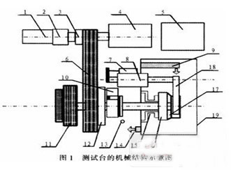
The main components of the car synchronizer test system are: structural table body, variable frequency motor, servo motor, inertia flywheel, tested synchronizer, shifting manipulator, circulating lubrication system, manipulator control box, control cabinet, various detection sensors, PLC, Computer, etc., the mechanical structure of the test bench is shown in Figure 1.
Note: 1. AC servo motor (0.85kW); 2. Reducer; 3. Clutch; 4. AC variable frequency motor (3 kW); 5. Robot hydraulic pump station; 6. Pulley; 7. Displacement sensor; Cylinder; 9. Lubricating oil injection port; 10. Encoder (low speed); 11. Combined inertia flywheel; 12. Clutch; 13. Speed ​​sensor (high speed); 14. Lubricating oil return port; 15. Two-component force Sensor; 16. gear cone; 17. synchronizer; 18. shift fork; 19. work compartment.
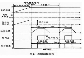
The test bench can perform three main tests on a certain type of synchronizer: continuous test, inertial test and squeeze test, continuous test and inertial test to measure the dynamic friction coefficient and wear resistance of the synchronizer, and the squeeze test is used to measure the synchronizer. Static friction coefficient, the test is carried out in the lubricating oil environment from room temperature to 120 °C. By analyzing and calculating the measurement data of the test bench, the friction performance and wear resistance of the synchronizer are observed and recorded, thereby making the performance of the synchronizer Evaluation, wherein the continuous test process is shown in Figure 2.
2 test system design
The core of the whole test system is the measurement and control part. Firstly, it is required to monitor the operation status of the system in real time to ensure the safe and reliable operation of the system. At the same time, in the test process, it is required to collect the displacement, rotation speed, synchronous torque, axial force and lubricating oil in real time. A series of signal data such as gentle flow rate, through processing the collected signal data and the characteristic curve drawn therefrom, analyze and evaluate the relevant performance of the measured transmission synchronizer. The block diagram of the measurement and control system is shown in Figure 3.
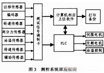
The measurement and control system consists of PLC, computer, various sensors, signal test conditioning card, drive and control motor. The test system is jointly controlled by the computer and PIC. The computer as a host computer has a good human-computer interaction function. It is responsible for monitoring the entire measurement and control system, sending commands and data to the PLC, realizing control of the field devices, and collecting by data analysis software. The test data is further processed to test the performance of the synchronizer.
Because PLC has the advantages of convenient operation and high reliability, it can meet the requirements of test system control well. Therefore, PLC is used to collect on-site signals and output control signals; it is responsible for direct control and monitoring of field devices, including motion control of shifting robots. The motor speed is adjusted, the transmission oil temperature is controlled, etc.; the sensor is responsible for collecting the signal of the scene, and the signal is converted into an analog quantity and transmitted to the PLC and the computer through the signal test conditioning card.
It should be pointed out that before the test starts, the gear position of the transmission must be preset, and the gear selection position sensor and the gear position sensor data corresponding to each gear are stored in the storage area of ​​the PLC, and the control of the robot is also controlled. Parameters such as the gear force of each gear, the gear speed, and the gear position compensation are stored in the storage area of ​​the PLC. During the test, the shift process is accurately and quickly simulated by quick query of these data.
3 system implementation
The measurement and control system is integrated with computer and PLC.
As the upper computer, the corresponding control program in the computer is developed based on the Windows2000/XP platform system. The user-friendly user interface can realize the automatic control of the test bench and the storage and analysis of the test data. The main functions of the test are:
1) Review, delete, analyze, and print historical test data or graphs;
2) Real-time display of the status of the equipment under test and possible error faults, and automatically respond to the error level (warning, error, serious error, fatal error);
3) The test program can be preset, including parameters such as axial force, loading time, unloading time, speed difference, lubricating oil temperature, etc., and can edit, save, download and print the synchronizer parameters and test conditions;
4) Continuously record relevant data in the test process continuously, display all measurement and calculation data in real-time graph, and generate corresponding change curve analysis map;
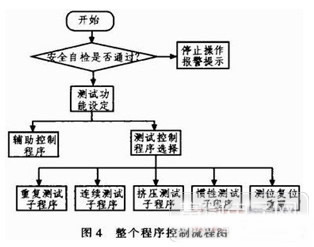
As the lower position machine, PLC is responsible for the control and monitoring of the field equipment. The control program in PLC is written by the TwinCAT PLC programming software of Beckhoff Company of Germany. The whole program control flow is shown in Figure 4.
The functions implemented by the control program in the PLC are mainly:
1) Collecting data Because there is usually strong electromagnetic interference in the test environment, if the corresponding anti-interference measures are not taken, it will enter the measurement and control system in the form of conduction and radiation, which will seriously affect the test results, so it should be correspondingly based on hardware and software. Processing, the corresponding electromagnetic shielding should be adopted on the hardware, multiple filtering circuits should be set in the test signal modulation card, and the I/O module of the PLC should be electrically isolated by photoelectric isolation function; the corresponding algorithm is used for filtering processing on the software to further reduce the interference effect. .
2) Safety protection When the improper operation or testing of the synchronizer parts assembly occurs prematurely or other faults (motor overload, overspeed, over temperature, etc.), the test rig can be automatically and automatically stopped, and the inverter has overcurrent, overload, Over-voltage, under-voltage, over-heat, short-circuit and cooling fan abnormal protection, overload and overspeed protection for the motor, overspeed, over-torsion and over-temperature protection for the system, all alarm signals display the cause of the fault or fault code through the main control computer; emergency Parking is a necessary hardware function, which can be performed manually or automatically. When the emergency stop is stopped, the loading mechanism is in the middle position. The motor stops urgently through the brake unit, the robot picks up the neutral gear, and the alarm sends an alarm.
3) The control shift PLC extracts the corresponding data in the storage area according to the control command sent by the computer, and performs the corresponding shifting action; at the same time, the computer monitors the completion of the shifting operation by reading the corresponding sensor signal, if the selection is not in place or When the shift is timed out, the neutral gear will be forced immediately to play the role of safety insurance; when the gear selection is timely and accurate, the next command will be issued.
4 Conclusion
The Synchronizer Test System is an automatic control electromechanical integration device that integrates signal acquisition and processing, electronic circuits, and mechanical structures. It can perform typical long-term, high-repetition test projects with stable and reliable operation. Level has important practical value.
XLPE Insulated Electrical Cable For Rated Voltage 3.6/6KV~26/35KV
For XLPE insulated power cable, either chemical method or physical method is employed to transform the molecular structure of PE from chain into three-dimensional network, i.e. thermoplastic PE is transformed into thermo setting XLPE. After cross-linking, the thermal and mechanical properties of PE have been greatly improved while its excellent electrical property are still retained.
The maximum permissible operating temperature of the conductor of a XLPE insulated power cable is 90℃ which resistance is higher than that of PVC or PE insulated power cable. The cable has the advantage of simplicity in construction, lightness in weight, convenience in application besides its excellent electrical, thermal, mechanical and anti-chemical corrosion properties. It can also be laid with no limitation of level difference along the route.
1. Product standard
The product is manufactured according to the standard of IEC60502-2 [Extruded solid dielectric power cables for rated voltages from l KV (Um=1.2KV) to 35KV (Um=40.5KV)", BS, DIN and ICEA upon request.Include 33kv Cable, 20kv Cable ,15kv Cable,11kv Cable, all of them are manufactured according to the standard.
2. Applications
The product is suitable for use in power transmission and distribution lines with rated power frequency voltage 3.6KV/6KV~26/35KV.
3. Operating characteristics
Rated power-frequency voltage U0/U: 3.6/6KV~26/35KV.
Max. Permissible continuous operating temperature or conductor:90℃.
Max. short-circuit temperature of conductor shall not exceed 250℃. (5s maximum duration)
The ambient temperature under installation should not below 0℃.
The bending radius of a single-core cable should not less than 20 times of the cable diameter.
The bending radius of a three-core cable should not less than 15 times of the cable diameter.
4. Voltage designation
The rated voltage of the cable for a given application shall be suitable for the operating conditions in the system in which the cable is used, and is expressed in the form of U0/U (Um) KV. Where:
U0-The rated power-frequency voltage between conductor and earth or metallic screen, for which the cable designed;
U-The rated power-frequency voltage between conductors, for which the cable designed;
Um-The maximum value of the [highest system voltage" for which the equipment may be used.
5. The values of U0 recommended for cables to be used in three-phase systems are listed below.
System category A-This category comprises those systems in which any phase conductor that comes in contact with earth or an earth conductor, is disconnected from the system within 1 min.
System category B-This category comprises those system which under fault conditions, are operated for a short time with one phase earthed. This period should not exceed 1h. For a longer period, not exceeding 8h on any occasion, can be tolerated. The total duration of earth faults in any year should not exceed 125h.
System category C-This category comprises all systems which do not fall into categories A and B.
6. Construction of cable
3.6/6kV~26/35kV, Single-core, XLPE insulated, power cable
3.6/6kV~26/35kV, Single-core, XLPE insulated, steel tape armored power cable
3.6/6kV~26/35kV, Single-core, XLPE insulated, steel wire armored power cable
3.6/6kV~26/35kV, Three-core, XLPE insulated, power cable
3.6/6kV~26/35kV, Three-core, XLPE insulated, steel tape armored power cable
3.6/6kV~26/35kV, Three-core, XLPE insulated, steel wire armored power cable
Single Core Aluminium Conductor,Three Core Copper Conductor,Three Core Aluminium Conductor,33kv Cable,20kv Cable,15kv Cable,11kv Cable,69kv Cable
Huayuan Gaoke Cable Co.,Ltd. , https://www.bjhygkcable.com