In the next few years, radar will play an important role in the development of Advanced Driver Assistance Systems (ADAS). With the expansion of its role, radar transceivers, signal processing and automatic hedging will make the vehicle ADAS system more and more like the tactical system in combat aircraft, which will have a great impact on the automotive system design basis.
This article refers to the address: http://
Why is the radar?
Much of the discussion of ADAS has focused on passive vision systems that use visible wavelength cameras. Ralf Reuter, a radar systems engineer at Freescale Semiconductor, has convincingly demonstrated the role of the 77-GHz radar.
Reuter said in a recent interview: "The important point is that [ADAS sensing technology] only radar is weather-independent. Cameras have an advantage in identifying targets, and radar is better at detecting objects and measuring their speed."
Reuter explained that for these reasons, many early systems that value detection and risk classification assessments choose radar. He pointed out: "In Europe, there is a great demand for truck emergency braking systems. It is radar based."
The radar system starts a simple mid-range system and looks straight ahead at the entire road. However, it will soon be developed into a multi-sensor system that includes both long-range forward-looking and short-range 360-degree hazard assessment functions, as shown in Figure 1.
Although the optical vision system is very mature, the advantages of the radar system will make it more perfect. Reuter predicts that in the near future, multi-camera complex systems with target recognition will be able to fuse video and radar data to create dynamic models of the surrounding world.
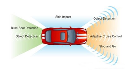
Figure 1. The radar system is capable of performing a forward search and observing the surroundings of the vehicle.
Acquire the Signal
Understanding the impact of radar on automotive system design begins with an understanding of the sensor. Most automotive radar designs are willing to use the 24 or 77-GHz free band. The transmitter is typically a frequency modulated continuous wave (FMCW) design that emits "å•å•¾": a fast change in the frequency domain, as shown in Figure 2.
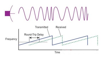
Figure 2. The vehicle-mounted radar will use the å•å•¾-type FMCW.
Reuter explained: “The biggest advantage of FMCW is that it simplifies the understanding of reflected signals. You can read the target range directly from the reflected frequency and derive the velocity from the Doppler shift. Produce CW compared to the pulse modulation scheme. It's not too complicated, it's easy to understand, it's very reliable. This is the biggest concern for vehicle manufacturers. They think that every euro that is spent on improving ADAS comes directly from corporate profits.
Receiving signals also requires a low cost novel design. Collecting the reflected signal by collecting the orientation information requires a mechanical scanning antenna or a phased array antenna, and incorporates a digital bunching algorithm. Behind the antenna is typically a homodyne receiver with many channels, which is required for antenna design - for simple rotating antennas, 16 for an array.
Reuter said: "The receiver output is the baseband signal in the DC-20-MHz band." Designed to achieve a good azimuth resolution system will have 8 to 16 channels, requiring 8 to 16 high-speed analog-to-digital converters (ADCs) .
Extract information from å•å•¾
The digital baseband signal from each channel flows into a Fast Fourier Transform (FFT) block to achieve a transform of up to 2K samples. Reuter said: "In the past, performing FFT meant that many FPGAs were needed. Today, the trend is for 32-bit microcontrollers that integrate floating-point DSP accelerators." The bunching system can extract range and velocity data from signals using two FFTs. ,As shown in Figure 3.
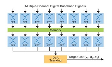
Figure 3. FFT configuration for bunching and range and velocity estimation.
In effect, this front-end processing unit processes the input multiple FMCW analog channels to form a digital code stream of azimuth/range/speed arrays. This data stream enters one or more CPU cores, and software supported by other accelerators infers whether objects appear around the vehicle, the location and properties of the objects.
Reuter explained: “You need to identify the targets, separate them from the background, and choose the most critical one. You may need to process 200 targets, so the calculations can be very complicated, especially extracting angle information.â€
The physical configuration of the system is also becoming more complex. Reuter said that the current processing of the sensor itself is rare. Instead, the ADC has a dedicated analog interface, a dedicated digital interface for signal processing hardware for the FFT, and a microcontroller with other interfaces to extract and classify the target. The target information is input to the Vehicle Control Area Network (CAN) or FlexRay bus, which is interpreted and analyzed by the central CPU cluster.
The entire pipeline has great bandwidth and latency requirements. Reuter said that the CPU's interpretation of the data is generally presented to the driver in a graphical display, that is, the front-end multi-function display that he can observe through the windshield. This hybrid display requires no more than 50-ms update intervals and a more challenging 50-ms maximum delay. Otherwise, the image will be very unstable, and the image through the windshield will be delayed, which may cause the driver to misjudge.
As the system evolved from one sensor to multiple sensors that support bunching capabilities to achieve camera data fusion, the interconnect architecture has also changed. Reuter said: "There is a need to use Ethernet to reduce costs." However, the system still requires real-time work, bringing with it how to ensure the real-time nature of Ethernet.
Everywhere is the future of interference
As long as no one around uses radar, on-board radars are generally more reliable. However, this has obvious problems: more and more vehicles use radar, so there is inevitably interference between devices. Reuter says that you can change the modulation rate to reduce interference. Finally, the coded hopping pattern is used instead of a simple frequency change, so each car can recognize its own flaws.
This change preserves the architecture of the early systems and most of the hardware, but to implement complex extraction and analysis functions, each system is required to recognize reflected signals from its antenna.
Moreover, there is a problem that is not easy to solve: the interference generated by fixed equipment. Reuter reminded: "The immediate problem is that European tunnels use high-power radars to identify vehicles. Their transmitters can cause in-vehicle radars to fail."
A more scientific and sensitive issue is that the key part of the astronomical object's radiation spectrum lies in the 77-GHz band. In densely populated areas, more and more in-vehicle radars can strongly interfere with astronomical RF signals. Reuter reminded: "There are regulations in Japan that require the transmitter to be turned off within 1,000 kilometers of the RF telescope. This may cover the entire country."
å•å•¾ Modulators, digital bunching, target recognition, hazard assessment, guard hopping, interference, etc. – these sound like new combat aircraft, not trucks and cars. In fact, ADAS inherits many of the technologies of military systems. This is not surprising. When the weather gets worse and the car gets blocked, it is like a war.
Rectifier Diode A semiconductor device used to convert alternating current into direct current. The most important characteristic of a diode is its unidirectional conductivity. In the circuit, current can only flow from the positive pole of the diode and the negative pole flows out. Usually it contains a PN junction with two terminals, positive and negative. Its structure is shown in the figure. The carriers in the P region are holes, and the carriers in the N region are electrons, forming a certain barrier in the P region and the N region. When the applied voltage makes the P region positive with respect to the N region, the barrier is lowered, and the storage carriers are generated near the two sides of the barrier, which can pass a large current and have a low voltage drop (typically 0.7V), which is called positive. Wizard status. If the opposite voltage is applied, the barrier is increased to withstand a high reverse voltage, and a small reverse current (called reverse leakage current) is called a reverse blocking state. The rectifier diode has significant unidirectional conductivity. The rectifier diode can be fabricated from materials such as semiconductor germanium or silicon. The silicon rectifier diode has a high breakdown voltage, a small reverse leakage current, and good high temperature performance. Usually high-voltage and high-power rectifier diodes are made of high-purity single crystal silicon (it is easy to reverse breakdown when doping more). This device has a large junction area and can pass a large current (up to thousands of amps), but the operating frequency is not high, generally below several tens of kilohertz. Rectifier diodes are mainly used in various low-frequency half-wave rectification circuits. If full-wave rectification is required, they must be connected to a Rectifier Bridge.
Rectifier Diode,Smd Diode,Smd International Rectifier,General Rectifier
Dongguan Agertech Technology Co., Ltd. , https://www.agertechcomponents.com