Foreword
This article refers to the address: http://
With the advancement of science and technology, the development of automobiles has entered a new era. Automotive electronics (automotive air conditioning controllers) have also become a hallmark of automotive performance. Automotive driveshafts are an important part of automotive construction (automotive electronic control technology), so the design of automotive driveshafts becomes even more important. Then, how to design a high-performance automotive drive shaft, the author through the collection and collation of materials, from the basic requirements of automotive drive shaft design, factors to consider and optimization of automotive drive shaft design and other aspects.
Basic requirements for automotive drive shaft design (automotive control system):
1. When the relative position of the two connected shafts is changed within the expected range, the power can be reliably transmitted.
2. Ensure that the two shafts connected are running at the same speed as possible.
3. Additional loads, vibrations, and noise due to the included angle of the gimbal should be within the allowable range.
4. High transmission efficiency, long service life, simple structure, convenient manufacturing, easy maintenance, etc. Chapter III Isuzu universal drive shaft structure analysis and selection Because the Isuzu truck wheelbase is not too long, and the load capacity.
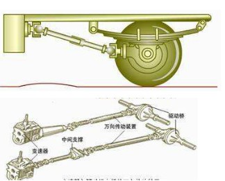
Universal transmission between the transmission and the transaxle
Several aspects to consider when designing an automotive drive shaft
The hollow drive shaft has a small mass, can transmit a large torque, and has a higher critical speed than the solid drive shaft, so the drive shaft tube adopts a hollow drive shaft.
The length and angle of the drive shaft and their range of variation are determined by the overall layout of the vehicle. It should be designed to ensure that the spline sleeve and the spline shaft have sufficient mating length when the length of the drive shaft is at the maximum value; and when the length is at a minimum, the two do not die. The angle of the drive shaft affects the life of the universal joint cross shaft and needle bearing, the efficiency of the universal joint and the unevenness of the cross shaft. The range of variation is 3.
The automobile drive shaft is often in a high-speed rotation state, so the material of the shaft is selected from the mechanical parts manual. 40CrNi is selected for the very important shaft and has high torsional strength.
Automotive drive shaft tube selection
The transmission shaft tube is made of low-carbon steel plate with uniform wall thickness, (1.5-3.0mm) large diameter, thin wall, easy mass balance, high torsional strength, high bending rigidity, and suitable for high-speed rotating electric welded steel pipe.
The telescopic spline selects a rectangular spline to compensate for the change in length between the universal joints at both ends of the drive shaft as the vehicle travels. In order to reduce the resistance and wear, the spline tooth is phosphated or sprayed with nylon, and the outer layer is provided with a dust cover, and the gap is small to avoid vibration of the transmission shaft. The spline teeth and the keyway are assembled in corresponding markings to maintain the dynamic balance of the drive shaft assembly. The unbalance of the drive balance is compensated by the balance plate welded by the welding tube. When loading, the end of the telescopic spline of the drive shaft should be close to the transmission to reduce its axial resistance and wear. Its structure is as follows:
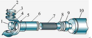
Universal drive shaft - spline shaft structure diagram
1-cover; 2-cover; 3-cover pad; 4- universal joint fork; 5--fueling nozzle; 6-retractable sleeve; 7-sliding spline groove; 8-oil seal; 9-oil seal cover; tube
Automobile drive shaft design optimization theory
The optimization method of the design of the automobile transmission shaft is a design method that optimizes the application mathematics away from solving practical problems. The so-called optimization design is based on the design model and initial design parameters, select an optimization method to program, calculate the parameters and optimize the performance indicators. Take the design of the automobile drive shaft as an example for analysis. The objective function of this design is a binary function. The size and variation of the function value can be drawn into an intuitive graph by using the contour. It can be set to f(x1, x2)=Ci so that a series of plane curves can be obtained. The image expresses the law of the change in the value of the function, and can finally get the minimum point of the function (ie the most advantageous). The minimization of the optimal process is to start from the X0 point, in a certain direction, in a certain step, step by step to the most advantage, until the required conditions are met.
Trial design of automobile drive shaft design optimization program
The following is a subroutine of an optimization constraint written in C:

Or you can use the special design software such as matlab to optimize the program. Finally, if the initial value is: D=63.5mm, d=58.5mm, S=479.093mm2δ=2, nmax=4000r/min, Ts=1.02×10⁶N*mm
[Ï„]=125N/mm2 can be optimized as:
D=59.34mm, d=56.14mm, S=290.2548mm2.
to sum up
The automobile transmission shaft is an indispensable part of the automobile structure. This paper mainly introduces the basic requirements of the design of the automobile transmission shaft, several aspects to be considered when designing the automobile transmission shaft, and the procedures for optimizing the design of the automobile transmission shaft prepared by the C language. The basics of automotive drive shaft design.
The Brushless dc motor consists of a motor body and a driver, and is a typical mechatronic product. The driver is composed of power electronics and integrated circuits, and its functions are: receiving start, stop, and brake signals of the motor to control start, stop, and brake of the motor; accepting position sensor signals and forward and reverse signals for controlling the inverse The power bridges of the variable bridges are turned on and off to generate continuous torque; the speed command and the speed feedback signal are accepted to control and adjust the speed; provide protection and display, etc.
Brushless motor,Brushless dc motor,Bldc motor,Brushless motor price,Brushless dc electric motor,Bldc motor price
Shenzhen Maintex Intelligent Control Co., Ltd. , https://www.maintexmotor.com