Today, we introduce a national patent for invention, ultrasonic water meter. The patent was applied for by Tianjin Jinfeng Science and Technology Development Co., Ltd. and was authorized on May 11, 2018.
Content DescriptionThe invention relates to the field of water meter devices, and in particular to an ultrasonic water meter.
Background of the inventionWith the continuous promotion of smart card technology, non-contact smart cards have been widely used in bus, taxi, oil and other small payment applications for their convenience and security. In the intelligent water fee charging application where the water meter and the smart card reader are integrated, the user pre-stores a certain amount of money in the smart card. When paying, the user only needs to use the smart card, and the reader integrated with the water meter is provided according to the water meter. The use of water resources data, deducting the corresponding amount from the money stored in the smart card, completes the process of paying the water fee.
At present, the ball valves of the ultrasonic water meter are installed sideways. For example, a Chinese patent discloses a stainless steel ultrasonic valve control water meter detection pipe segment, 201710756506.9. In the side of the ball valve into the pipe section, and then tightened by a short section of the pipe, the disadvantage of this structure is that the workers in the assembly is very inconvenient, you need to first put the ball valve, and then the ball valve is fixed with the screw fixed, and finally screw Into the pipe section, inconvenient to operate, time-consuming and laborious. Another example is the Chinese patent discloses a high stability, start small ultrasonic water meter pipeline structure, patent No. 2014200084430, this method has the disadvantage that if the transducer mounting hole is far from the water meter at both ends of the case This installation method is very difficult to install, the other way is to set a counterbore downward from the position of the transducer mounting hole, and install a bracket in the counterbore, such as an ultrasonic water meter disclosed in the Chinese patent, patent number, This kind of structure needs to rotate the bracket, constantly adjust the angle of the reflection sheet, and the installation speed is very slow.
Summary of the InventionThe purpose of the present invention is to overcome the deficiencies of the above techniques and provide an ultrasonic water meter that is easy to assemble and disassemble and reduces the subsequent cost.
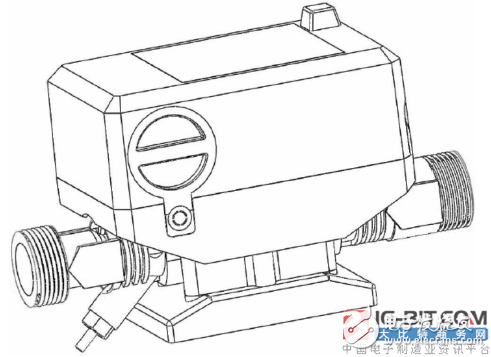
The figure is a schematic structural view of the invention
In order to achieve the above object, the technical solution adopted by the present invention is: an ultrasonic water meter, which is characterized by comprising a water meter body, a valve body, a valve seat, a valve ball, a left fixed seat, a right fixed seat, and a reflection sheet; The transducer mounting holes are respectively arranged on two sides of the transducer, and two T-shaped mounting grooves are correspondingly arranged on the sidewalls of the transducer mounting holes. T-shaped connecting ears are fixed on both sides of the reflector, and the reflector and the T-shaped connection are connected. The ears are integrally formed, and the T-shaped connecting ear is matched with the T-shaped mounting slot. The transducer is pressed on the upper part of the T-shaped connecting ear to fix it in the transducer mounting hole, and the transducer is fixed to the ultrasonic pipe segment through the pressing piece. The valve body is mounted on the body of the water meter. The valve body has a valve chamber communicating with the body of the water meter. An entrance is provided at the bottom of the valve body. The left and right fixing seats are provided with through holes. The diameter of the through hole is smaller than that of the valve ball. The outer diameter of the left fixed seat is provided with a pin shaft, the right fixed seat has a shaft sleeve matched with the pin shaft, the valve ball is placed between the left and right fixed seats, and the pin shaft is inserted into the sleeve to be installed from the entrance. Into the valve chamber, the valve base and the inlet are connected by bolts to the ball And the left and right seats are sealed in the valve chamber.
Compared with the prior art, the device changes the installation manner of a conventional valve ball and integrally casts and forms a valve body in the middle of the water meter body. The valve body has a valve chamber and can be a valve ball. The device first passes the valve ball to the left and right. After the fixing seat is fixed, it is put into the valve cavity and the valve base bolt is fixed at the bottom. The valve ball can be quickly installed through the device, the overall structure is compact and beautiful, and the assembly efficiency of workers is greatly improved. Two T-shaped mounting slots are cut on the corresponding two side walls of the conventional transducer mounting holes for assembling T-shaped connecting ears. Two T-shaped connecting ears are integrally formed on both sides of the reflector, and the volume is very small. It occupies a very small space and can be slid in from the top of the T-shaped mounting slot without the need of secondary adjustment. It is very easy to install and greatly improves work efficiency.
A water case is provided on the body of the water meter, a battery compartment is installed on one side of the water meter case, the battery compartment is opened in both directions, a sealing cover is installed at the opening position, and the sealing cover is connected with the water meter case through the bolt. One side of the water case vertical to the axis box of the battery compartment is provided with a complex capacitance chamber. The one side of the complex capacitance chamber has an opening, and a sealing cover is installed at the opening position, and the sealing cover is connected with the water watch case through bolts. There are sealing rings on both sides of the through hole. There is a gasket between the valve seat and the left and right fixing seats. The two sides of the left and right fixing seats are respectively provided with slots, and the position corresponding to the slots on the valve cavity is provided with a positioning plugboard matched with the slots.
The beneficial effects of the present invention are: compared with the prior art, the device changes the installation manner of the traditional valve ball, and integrally casts and forms a valve body in the middle of the main body of the water meter. The valve body has a valve cavity and can be a valve ball. After the valve ball is fixed by the left and right fixing seats, it is put into the valve cavity and the valve base bolt is fixed at the bottom. The valve ball can be quickly installed through the device, the overall structure is compact and beautiful, and the assembly efficiency of workers is greatly improved. Two T-shaped mounting slots are cut on the corresponding two side walls of the conventional transducer mounting holes for assembling T-shaped connecting ears. Two T-shaped connecting ears are integrally formed on both sides of the reflector, and the volume is very small. It occupies a very small space and can be slid in from the top of the T-shaped mounting slot without the need of secondary adjustment. It is very easy to install and greatly improves work efficiency.
Soft Starter,Ac Motor Soft Starter,Soft Starter For Machinery,3-Phase Soft Starter
Zhejiang Kaimin Electric Co., Ltd. , https://www.ckmineinverter.com