Recently read the literature, which mentioned a crowbar circuit, had not been in contact before, the two days spent a little time to study it. This article is actually an online article found in English, written and easy to understand. I (artist) feel pretty good, translated it out, the original text is awkward, I made some abridgement.
Crowbar circuit
The crowbar circuit is an overvoltage protection circuit. The design idea of ​​this circuit is to short the power supply when the power supply voltage exceeds a predetermined value, and to pull down the power supply voltage by a short circuit. At this time, overcurrent protection devices such as fuses on the power supply path act to shut off the power supply to prevent damage to the power supply. From this mechanism, it can be seen that this circuit requires the power supply to withstand short-term short-circuit conditions without damage, otherwise it protects the back-end equipment but sacrifices the power supply equipment.
Crowbar Chinese meaning is a crowbar. When I first saw the word, I first thought of the lever, thinking that this circuit uses some kind of leverage principle. However, it was later discovered that the name of this circuit is not related to leverage. The so-called Crowbar circuit actually means that it is like throwing a crowbar (or other thick conductive rod) on the power supply wire to short-circuit it. This name is very uncultured!
Components such as thyristors are commonly used in Crowbar circuits. This type of component is normally non-conductive but can be turned on by a voltage or current signal on the control terminal. When the thyristor turns on, its turn-on voltage drop is about 1-2V. The Crowbar circuit generally does not use a transistor or field effect transistor to short the power supply because when the power supply is short-circuited, the base current needed to maintain the conduction of the transistor cannot be provided. Once the SCR is turned on, it does not need a control signal.
Basic crowbar circuit
The following figure shows a typical Crowbar circuit.
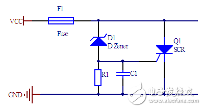
When the power supply voltage exceeds the regulated voltage of the zener diode, D1 conducts. When the power supply voltage exceeds the regulated voltage of the zener diode plus the turn-on voltage of the thyristor, the SCR turns on, pulling the power supply voltage down to 1-2V. The thyristor will not turn off until the current flowing through the thyristor decreases to nearly zero. The capacitance in the circuit is used to ensure that it will not be falsely activated by interference.
If the power supply's ability to output current is unlimited, the crowbar circuit will be quickly destroyed, so the output current of the power supply must be limited. The simplest method is to install a fuse or the power supply itself is a current-limiting type.
One disadvantage of this circuit is that it is difficult to accurately control the turn-on voltage. After all, the regulated voltage of the zener diode is only fixed, and the zener diode has a relatively large discrete type (2-5 %) and is also affected by the temperature. The SCR's turn-on voltage dispersion is also quite large. Therefore, when the power supply voltage is relatively low, we need to improve the above circuit to make the control voltage more accurate.
Accurate crowbar circuit
The opening voltage of the circuit below must be more accurate.
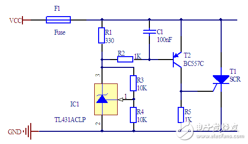
The TL431 is an inexpensive voltage source chip that can output voltages between 2.5 and 36V. Use it to solve the problem of large dispersion of the Zener diode, and the voltage stability is much better than the Zener diode.
The transistor T2 is used to solve the problem of large dispersion of the SCR turn-on voltage. The transistor turns on the thyristor when Vbe is greater than 0.6V. Due to the amplification effect of the transistor, a small change of the power supply voltage can generate a large voltage change at the control terminal of the thyristor. Although the transistor is also affected by temperature, the stability of the entire circuit turn-on voltage is much smaller than that of the original circuit.
The reference voltage of the TL431 is 2.5V, so the output voltage of the TL431 in the above circuit is 5V, and the turn-on voltage of the crowbar circuit is between 5.6 - 6.0 V. This circuit can protect 5V-powered devices.
Di/dt protection
The above circuit still has some areas for improvement. When the inflow current at the control terminal of the thyristor is only a little higher than the triggering on current, only part of the thyristor's internal start is turned on. It takes a certain amount of time for the thyristor to fully turn on. During this time, a large amount of current passes through a part of the thyristor, and it is easy to damage the thyristor. The thyristor chip manual has an index called maximum di/dt. The thyristor is safe only if the rate of change of the current through which the thyristor flows is less than the maximum value specified by this index. Typically, a 12A thyristor has a maximum di/dt of 100 A/μs.
The input to the power supply of the load usually has a very large capacitance. When the Crowbar circuit is working, this large capacitor will charge the thyristor with a large amount of current. In particular, large-capacity ceramic capacitors generate considerable di/dt pulses. One way to protect the thyristor against high current surges is to connect an inductor in series and limit the di/dt using an inductor. The required inductance can be calculated as:
U = L*di/dt
L = U/(di/dt)
In the above circuit, the turn-on voltage is about 6V, and the turn-on voltage drop of the thyristor is about 1V, so U = 6V - 1V = 5V. Assuming that the thyristor can withstand a di/dt of 100 A/μs, the inductance must be no less than 50 nH. In addition, it must be ensured that the inductor can withstand sufficient current, at least until the fuse blows.
Another crowbar circuit based on TL431
The TL431 chip manual gives a reference circuit as follows.
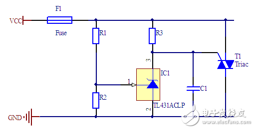
When the voltage at the reference input of the TL431 is less than 2.5V, the current flowing through the TL431 does not exceed 400 μA, so the voltage drop across R3 is small. When the power supply voltage increases so that the TL431's reference input voltage exceeds 2.5V, the TL431 turns on and the voltage drop across R3 increases until the thyristor turns on.
The operating voltage of this circuit is more accurate. However, bidirectional thyristors must be used, and ordinary unidirectional thyristors cannot work.
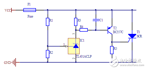
Improved crowbar circuit based on TL431
The above circuit can also be improved to further eliminate the effect of temperature on the thyristor.
Crowbar Controller
ON Semiconductor has a dedicated chip, the MC3423, to control the voltage more accurately while ensuring that the thyristor turns on quickly. With a simple resistor divider circuit, the turn-on voltage can be set between 4.5 V and 40 V.
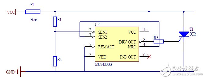
Compared with the previous circuit, the disadvantage of this circuit is slightly higher power consumption and higher turn-on voltage.
10 Inch Woofer,10Inch Full Range Speaker,Neodymium Woofer Driver,10Inch Mid Bass Speaker
Guangzhou BMY Electronic Limited company , https://www.bmy-speakers.com