Power Line Communication PLC (Power Line Communication) technology is a communication technology that uses high / low voltage lines in distribution networks to transmit high-speed data, voice, images and other multimedia business signals. The purpose is to provide users with a "no new" through low-voltage lines Line (None Wire) 's broadband access solution; while using medium voltage lines to provide a reliable data transmission platform for distribution network automation. Since the development prospects of this technology are very promising, as early as the early 1990s, some countries began to conduct research in this area, but due to the immature technology, the development rate is slow. Since the beginning of the 21st century, with the breakthrough of PLC technology, the development speed of power line communication technology has accelerated significantly? At present, it is developing in the direction of practical use.
The power line is different from the ordinary communication line, and its channel has the characteristics of not constant and uncontrollable in the time domain. Therefore, effective technical means of anti-interference, anti-impedance mismatch, and anti-multipath fading must be adopted, and signal conflicts must be resolved before power lines can be used as transmission media to achieve high-speed data communication. Multi-carrier orthogonal frequency division multiplexing (OFDM) is an effective method to solve these problems. This technology uses the high-frequency spectrum resources of the power line to modulate data with multiple mutually orthogonal carriers, and finally transforms the serial data stream into parallel processing; its modulation and demodulation process can be realized by Fourier transform on DFT / IDFT . The INT51X1 chip launched by Intellon is the most perfect OFDM processing chip at present, it conforms to the HomePlug 1.0.1 technical standard, and the transmission rate can reach up to 14Mbps. Moreover, it integrates USB 1.1, Ethernet and MII / GPS interface, as well as ADC, DAC and AGC controllers, which is more convenient to use, thus providing an ideal solution for the research and development of PLC communication devices. 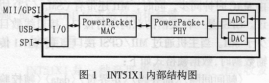
1 The functional structure and main features of INT51X1
INT51X1 is a MAC / PHY integrated transceiver dedicated to power lines. It uses Intel ’s proprietary power data packet (PowerPacket) orthogonal frequency division multiplexing technology. It has 84 sub-carriers, and uses ROBO / DBPSK / DQPSK modulation methods; Subcarriers are allocated according to the signal-to-noise ratio at the transceiver end to overcome the effects of noise and multipath fading; it does not require pilots to complete synchronization in low signal-to-noise ratio channels. Its internal structure is shown in Figure 1. It can be seen that it consists of I / O module, Power Pack MAC module, Power Pack PHY module and ADC / DAC module.
In INT51X1, PowerPacket MAC module mainly completes the link layer function, which is the core part of the chip. This module includes a reduced instruction set (RISC) processor core, a module containing OFDM data processing, encryption / decryption algorithm and channel optimization algorithm. Program memory (ROM), there is also a link sequence, data memory (RAM) and two direct data transfer channels (DMA). All data sent from the user to the power line network or from the physical layer can be processed in the MAC module through a certain algorithm. The MAC uses the carrier sense multiple access / collision avoidance (CSMA / CA) protocol to access the common power line channel, and is supplemented by the automatic retransmission request ARQ and power data packet priority mechanism, thereby ensuring the reliability of transmission. Moreover, because the power data packet priority level can be flexibly set, it makes INT51X1 have a stronger burst segment processing capability. Allowing multi-frame transmission on the power line greatly reduces the requirements on the network end and maximizes the network throughput, thus ensuring the shortest delay time and optimal signal stability. In addition, MAC also has a flow control function. These functions of INT51X1 can ensure that users can provide excellent service quality (QOS) even on particularly harsh power line channels.
PowerPacket PHY modules are mainly used to implement the physical layer functions, provide electrical means to establish, maintain and tear down physical connections, and ensure the transparent transmission of bit streams on power lines. This module is mainly composed of a physical layer logical sequence, a first-in first-out (FIFO) stack corresponding to the DAC channel of the MAC sublayer, and a forward analog channel. In addition, it also integrates automatic gain control (AGC) with an external operational amplifier. Features. Its forward analog channel contains a pair of high-speed 10-bit A / D and D / A converters with a sampling speed of 50Mbps. The reference voltage of this module is independent of the on-chip and can be operated with low power consumption. Then connect the operational amplifier and filter, and then connect to the power line through the power line coupling device.
The I / O module integrates various interfaces between the MAC and the host and peripheral devices, so the function is very rich. The interface with the host includes a USB interface, a media independent interface MII or a universal serial interface GPSI (optional), and a management data interface MDI; the interfaces with peripheral devices include an E2PROM interface SPI, a simulation interface JTAG, and a LED interface for operation status monitoring. Among these interfaces, MII is a standard industrial interface, and its sending / receiving is carried out in a four-bit parallel mode, and is synchronized by the MAC clock. At the same time, MII also has the CSMA / CD protocol. GPSI is a flexible two-way serial interface, the number of interface lines is less than MII. When the host transmits data with the INT51X1 through the MII / GPS interface, the data frame format is as follows:
<Interframe Space> <Preamble> <Delimiter> <data> <Frame Check Sequence>
The preamble is a 56-bit "1" and "0" phase sequence used for synchronization; the 1-byte delimiter is defined as D5H; the data format follows the IEEE802.3 standard? The final frame check sequence is 4 byte CRC check result.
The host computer can easily access the internal control / status register of INT51X1 through MDI, thus completing the setting of INT51X1 and monitoring the real-time running status of INT51X1. The control / status registers of INT51X1 are all 16 bit registers. The status register can reflect information such as link status, transmission rate, preamble decision, auto-negotiation, and fuzzy detection in real time. The definition of the control register is shown in Fig. 2, which can be seen from Fig. 2. Many functions can be realized through the control register.
After power-on, the initialization of INT51X1 is completed by reading the data written in advance to E2PROM through the SPI interface.
In addition to the above main functional features, PowerPacket's security performance is also very perfect. It adopts the 56-bit key management method of DES. In addition to the default key set by INT51X1, the user can also customize the key to ensure power line transmission Reliable and safe. 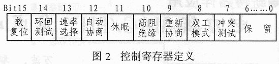
2 Pin description of INT51X1
INT51X1 adopts μBGA package, has 144 pins, chip power supply voltage is 3.3V, chip core power supply voltage is 1.5V. INT51X1 has three working modes: USB, PHY, HOST / DTE. Some of the multiplexed signal pins have different function definitions due to different modes. Taking the HOST / DTE mode as an example, the signal pins are defined as follows:
(1) Function of MII interface pins
MII-RX0 ~ MII-RX3: Receive data line;
MII-RXCLK: Receive clock line;
MII-RXDV: valid end for receiving data;
MII-RX-ER: Receive error indication terminal;
MII-COL: conflict detection;
MII-TX0 ~ MII-TX3: send data line;
MII-TXCLK: send clock;
MII-TXEN: send enable;
MII-CRS: carrier sense;
MII-TX-ER: Send error.
(2) Function of MDI interface pins
MII-MDIO: Management data input and output;
MII-MDCLK: Management data I / O clock;
SPI: interface pin;
SPI-DO: Data can be output to E2PROM through this terminal;
SPI-DI: data is read in from E2PROM;
SPI-CLK: SPI clock;
SPI-CS: Strobe E2PROM.
The other signal lines in the chip are the same in the three modes, including 26 control / data lines for analog front-end AFE (including ADC input, DAC output, AGC control of operational amplifier, etc.), 3 LED lines and 5 JTAG lines , 2 clocks, 2 test lines, and multiple power and ground lines; the selection of the three modes can be determined by the state of the two pins of MODE0 and MODE1.
Due to space limitations, detailed information about the pins will not be elaborated here. Interested parties can refer to relevant information. 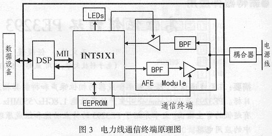
3 Application of INT51X1 in power line communication
As a power pack integrated transceiver, INT51X1 can use high-frequency power lines with poor high-frequency characteristics to achieve high-speed data transmission. Because the chip is highly integrated with the data processing function of the power pack and the external interface, it only needs simple initialization without complicated programming when it is used, and it is very convenient to use. Now I will introduce the application of INT51X1 with the research of the medium voltage distribution network OFDM communication system developed by the author as an example.
3.1 Mode selection
By setting the pins MODE0 and MODE1 of INT51X1, you can select the working modes such as INT51X1 USB, PHY or HOST / DTE. The specific selection methods are listed in Table 1.
Table 1 Selection method of working mode
| MODE1 | MODE0 | Selected mode |
| 0 | 0 | Keep |
| 0 | 1 | USB |
| 1 | 0 | PHY |
| 1 | 1 | HOST / DTE |
The USB mode actually treats the INT51X1 as a USB device connected to the USB host. PHY mode is to connect INT51X1 equivalent to an Ethernet physical layer device PHY with a microprocessor or Ethernet controller. The HOST / DTE mode treats the INT51X1 as a network host or a data terminal, and then connects to Ethernet PHY or other data devices through the MII interface. In this way, INT51X1 acts as a bridge between Ethernet and the power line network, thereby connecting those data devices to the power line network.
The application purpose of this design is to use the medium voltage power line to communicate with all the distribution automation devices on the medium voltage distribution network, so as to build a communication network for the distribution network automation. Obviously, this design should choose HOST / DTE mode.
3.2 Communication terminal design
The distribution automation device should be equipped everywhere along the distribution network. Its task is to collect the operating parameters of the distribution lines and various electrical equipment and send it to the distribution automation master station, while receiving related control commands from the automation master station. To control lines and power equipment. In order to transmit these parameters and commands with power lines, the author designed the communication terminal shown in Figure 3.
In this design, an analog front-end module (AF Mode) is designed on the power line side of INT51X1. This module contains an adjustable gain transmission amplifier and a reception amplifier. The transmission and reception branches are respectively connected with an LC bandpass filter. The pass band of the band-pass filter is 4 to 21MHz, which is the frequency band occupied by OFDM modulation. Coupling equipment (Coupler) is a special device that connects AFE to the power line. Its main function is to transmit high-frequency signals with low insertion loss, while preventing the power frequency current of the power line from entering the communication terminal. At the user side of INT51X1, TI ’s high-speed DSP (TMS320VC5471) is used. This DSP embeds the MII interface and connects to INT51X1. At the same time, it uses UART serial port to connect to the distribution automation device (Data Equipment in the figure). The data sent by the distribution automation device is packaged by the DSP according to the aforementioned MII data frame format, and transmitted to the INT51X1 via the MII interface, which is then converted into a Power Pack and sent to the power line, and then received by the destination communication terminal. The PowerPacket sent to this terminal from the power line is unpacked by INT51X1 and converted into MII frames, and finally transmitted to the automation device via DSP.
4 Conclusion
INT51X1 is a highly integrated single-chip power line transceiver, it is a replacement product of INT5130 + INT1000 sets of chips, and is also the mainstream product currently developing power line OFDM communication. The chip is powerful, flexible, and highly reliable. But according to the author's experiment, the transmission rate can only reach about 8Mbps, but can not reach the theoretical 14Mbps, but for power line communication, because its bandwidth requirements are not particularly large, it can fully meet the application needs.
Ultra Thin Battery,Ultra Slim Battery Pack,Thin Lithium Ion Battery,Ultra Light Optics Battery,Polymer lithium battery,Cylindrical Lithium Battery
Langrui Energy (Shenzhen) Co.,Ltd , https://www.langruibattery.com