As an indispensable part of the car, the throttle directly affects the safety of the car. Since the 21st century, most cars have replaced the conventional throttle with an electronic throttle. Compared with the old-fashioned pull-throttle, the electronic throttle controls the electronic signal by the depth of the accelerator pedal, so that the engine provides the matching power. The biggest feature is that the throttle opening can be controlled by the ECU. When the position of the accelerator pedal changes, the signal output from the electronic throttle can be used as a basis for measuring the accuracy of the electronic throttle automatic control. The electronic throttle detection system uses various schemes to evaluate the quality and reliability of the electronic throttle based on these real-time signals. Its performance testing.
This article refers to the address: http://
1 System test items and types
The main function of the electronic throttle is to convert the angle at which the driver steps on the accelerator pedal into a voltage signal proportional to it, and at the same time make various special positions of the accelerator pedal into contact switches, and the engine conditions such as idle speed, high load, acceleration and deceleration The electrical pulse signal is sent to the controller ECU of the electronically controlled engine to achieve optimal automatic control of fuel supply, fuel injection and shifting. The detection system is based on the type of electronic throttle, mainly adopting five kinds of detection schemes: specifically including dual signal detection, dual signal plus switching quantity detection, single signal detection, single signal plus switching quantity detection, and electronic throttle detection with KD device.
1.1 System Test Project
Most electronic throttles need to detect information such as synchronization, linearity, pedal force, etc. The specific definitions of these test items are as follows:
(1) Synchronization degree: The throttle outputs the equality of two signal values ​​at a certain stroke angle.
(2) Linearity: The difference between the theoretical voltage value of the throttle signal at a certain stroke angle and the actual voltage value.
(3) Free-stroke angle: refers to the pedal stroke angle at which the signal continues to change when the pedal begins to change angle.
(4) Pedal force: including pressure and elasticity, is the force curve of the pedal from idle speed to full stroke, and then from full stroke to idle speed.
(5) Throttle signal curve: including the idle signal and full stroke signal, the voltage output signal curve of the accelerator pedal from idle speed to full stroke.
(6) Hysteresis: At a given angle, the output pressure in two different directions of rotation is measured, and the hysteresis effect is the difference between the two output pressures. The maximum acceptable gap is 1% for Ua taxis.
(7) Repeatability: Under the same conditions, after 10 complete round trips, the recorded voltage difference cannot exceed the sensor with a given temperature of (23 ± 5) °C and any point in the same direction. O.5%.
(8) Tilt error: The formula is as follows:
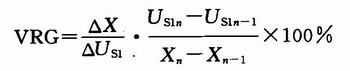
Where: VGR is the variable about the slope; △X is the distance between the bending points, the unit is mm; ΔUs1 is the difference between the full load Vs1 and the slow speed Vs1; Us1n and Us1n-1 are expressed at the position n and The voltage at n-1; Xn and Xn-1 represent the travel at position n and n-1.
1.2 System Test Type
The electronic throttle with KD is the most complicated throttle in the inspection project. In the throttle detection pattern with the angle as the abscissa, the throttle of the KD device needs to be converted into a stroke display, and the stroke can be calculated according to the formula L=2*R*sin(Θ/2). Where: L is the stroke; R is the radius of rotation; Θ is the angle of rotation. Where R is the set value and Θ is the angle sensor detection value. In addition, specific determination conditions for the range of idle position, force, stroke and voltage value can be referred to FIG. 1 and FIG. Figure 1 is a graph of the throttle ideal force with a KD device. It can be seen from the figure that the starting point of the KD throttle (2 mm on the abscissa) is the F1 point, the sensing point (at the 50 mm abscissa) is the F2 point, and the maximum force point is the F3 point.
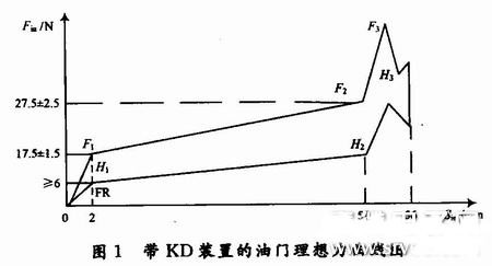
For example, if there is a KD force maximum point in the set 50~56 mm stroke, determine whether the value of the point force meets the setting requirement, and determine whether the distance from the set distance of 50 mm is less than the set value (in Figure 2 2 mm); from the KD force maximum point corresponding stroke plus 0.7 mm rear stroke position corresponding to the output electrical signal is 4.1 V (set value); from the output electrical signal 4.1 V position to the mechanical limit position (ie maximum travel) Position 56 mm point) Whether the stroke is greater than 3.3 mm, etc. Fig. 2 is a graph showing the determination condition of the throttle signal with the KD device.
Epoxy Coated Thermistor
Epoxy coated NTC Thermistor is small size and fast response. It also has the properties of high precision testing protection, good consistency and interchangeability as well as long-term stable operation. This type of thermistor can be used in air conditioner, central heating, clinical thermometer, automotive electronics, electronic calendar and so on.
Epoxy Resin Coated Thermistor,Thermistor Digital Thermometer,Air Conditioner Sensor,Automotive Thermistor
Feyvan Electronics Technology Co., Ltd. , http://www.fv-cable-assembly.com