First, the design of smart home security system based on single chip microcomputer
Abstract: This paper introduces a multi-node home security system design scheme with AT89S52 single-chip microcomputer as the control core and transmitted through DTMF public telephone network and CAN bus. The smart home security system integrates fire prevention, anti-theft and anti-gas, and can realize automatic detection and automatic voice dialing alarm. The circuits such as DTMF transceiver circuit, call circuit and CAN bus transmission are introduced in detail. The experimental results show that the system is functional and reliable, and the information transmission is real-time and reliable. It is suitable for security systems in home security or other places.
1 Introduction
The current security system can be realized by computer technology, IC card technology, communication technology, etc. The CAN bus is applied to the security system to promote the development of home intelligence. The application of DTMF technology to security systems requires no special wiring, no radio frequency resources, and no electromagnetic pollution. In this paper, a new intelligent home security system based on CAN bus and DTMF technology with AT89S52 single chip as the core is designed, which makes the real-time and reliability of the original community security system have a new level. The system can monitor the entire home security environment in real time. The scope of monitoring includes a series of unsafe factors such as indoor security, fire alarm and gas leakage. Once the above accident occurs, the alarm system will send out corresponding alarm information, use the voice to broadcast the alarm category, and provide the remote user and relevant departments with the alarm voice.
2 system overall composition
The system block diagram is shown in Figure 1. The single chip computer controls the DTMF transceiver circuit, the digital voice circuit, and the hook control circuit. The detector can quickly and accurately monitor the abnormal condition of the house, notify the controller in time after confirmation, and then control the telephone interface circuit by the single chip microcomputer to realize the analog off-hook, automatically dial the preset telephone number for voice alarm and notify the management center. . When the other party's response is detected, the alert state is automatically restored.
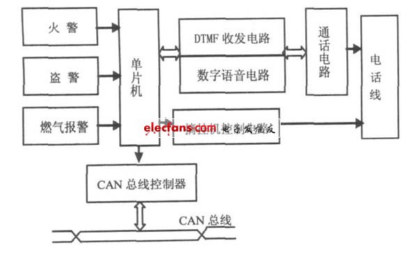
Figure 1 Block diagram of home security system
3 hardware design
The main control part of the system uses the AT89S52 microcontroller, which does not need to expand the external memory. The watchdog circuit uses a programmable serial EEPROM - X25045. The X25045 stores data information such as flag fields, phone numbers, alarm codes, and system settings. The digital voice circuit uses the digital voice chip ISD1420. In the system, the ISD1420 is only used as the basic recording and playback circuit, so all the address lines are set to 0, so the starting address of the playback is 0. The voice signal is picked up by the electret microphone, amplified from the amplifiers input from both ends of the M IC and M IC REF, and the audio signal after the power amplifier is used from the SP+ to be connected to the call circuit to send the voice signal.
3. 1 ringing detection and simulation hook unit
The system is at the two ends of the telephone line and is always in the monitoring state, which will not affect the normal operation of the telephone. Ring detection is performed when the system receives a ring signal. The ringing signal is connected to the P3. 4 port of the AT89S52 via three inverters. If no one answers after 5 rings, the system enters the automatic off-hook state. The single-chip microcomputer P1. 2 pin outputs a high level, the transistor V501 is turned on, then the relay K1 acts, and the load resistor is connected to the circuit to realize analog off-hook. After that, a current of more than 10 mA will appear on the telephone line. After the switching center detects this current, it will no longer output the ringing signal but will switch to the telephone. If the ringing signal does not reach the preset value, it will disappear, then the count value of the MCU will be cleared and the controller will not operate.
3. 2 DTMF transceiver unit
The DTMF transceiver circuit uses the DTMF signal encoding/decoding chip MT8880[5] chip. The MCU sends out the telephone number through the DTMF transceiver circuit to make a telephone alarm. The DTMF transceiver circuit is shown in Figure 2.
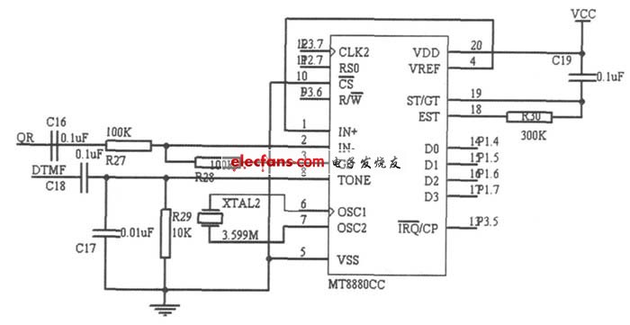
Figure 2 DTMF transceiver circuit
The MT8880 provides an interface to the microprocessor to control its transmit, receive, and operational modes. Its receiving part uses a single-ended input, consisting of R27, R28 and C16. Its input voltage gain is 1. The gain of the input signal can be adjusted by changing R28. Its transmitting part is composed of R29, C17, C18 and XTAL2. Its control part consists of R30 and C19. The IRQ /CP is connected to the P3. 5 pin of the microcontroller. When the MT8880 receives a valid dual-tone multi-frequency signal, the microcontroller performs interrupt processing. The IN-end of MT8880 is connected to the QR end of the call circuit TEA 1062, and the TONE end of MT8880 is connected to the DTMF end of TEA1062.
3. 3 call unit
The call circuit uses the telephone dedicated call integrated circuit TEA1062. When sending a message, the voice signal (from ISD1420) is input through the M IC + pin, and the DTMF signal (from MT8880) is input through the DTMF pin, amplified by the TEA1062, and sent to the telephone line from the LN pin. When receiving the signal, the signal is input from the IR pin through the eraser network, amplified and output from the pin QR, divided into two ways: one way to the ANA IN end of the ISD1420 for voice recording, and the other way to the IN of the MT8880. The terminal extracts the DTMF signal.
3. 4 CAN bus data transmission unit
The CAN bus data transmission unit consists of two parts, one is the CAN controller, which realizes the interaction and control of the bus data, and the other part is the CAN data transceiver, which realizes the network transmission of data.
The AT89S52 microcontroller realizes access to the bus by controlling the CAN controller. It is also responsible for the measurement and control of the functional unit. The CAN bus interface circuit is shown in Figure 3.
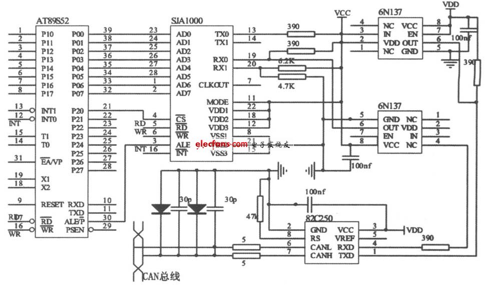
Figure 3 CAN bus interface circuit
The AT89S52 accesses the CAN controller SJA1000 through the interrupt mode. To enhance the anti-jamming capability of the CAN bus node, the SJA1000 is connected to the CAN bus driver PCA82C50 via the high-speed optocoupler 6N137. The CANH and CANL pins of the PCA82C50 are connected to a CAN bus by a 5 Ω resistor, which can be used as a current limiting function to prevent the PCA82C50 from being subjected to overcurrent surge.
4 software design
The software of the system adopts modular design, which mainly includes main program module, CAN communication module, ringing detection module, voice alarm module, DTMF transceiver module, etc. The main program and CAN communication module design are mainly introduced here.
4. 1 main program design
The main program mainly completes the call of each function module, detects the system input, and then performs judgment processing according to the system status. The program must perform the necessary initialization before the main loop, such as MT8880, ISD1420, SJA1000, and related flags. The main program flow is shown in Figure 4.
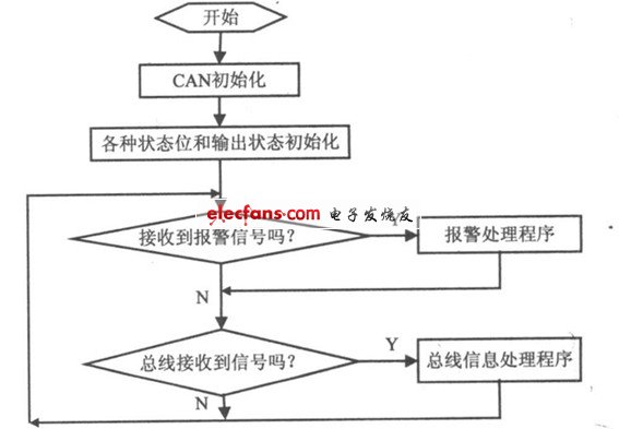
Figure 4 main program flow chart
These Tempered Glass include watch Screen Glass Protector, iPad Screen Glass Protector, other Tablet Screen Glass Protector, camera lens Glass Protector, etc.
Pls feel free to contact us if you are interested in these products, have any questions or special needed. We have the best sales team to service to you.
Look forward to your inquiry, and welcome to visit our factory.
Other Tempered Glass
Phone Glass Protector,Mobile Screen Guard,Iphone Protector,Mobile Tempered Glass,Tempered Glass Protector
Shenzhen Kantou IM Technology Co., Ltd. , https://www.kantou-im.com