Surface acoustic wave (SAW) technology is a cutting-edge field that emerged in the late 1960s, blending acoustics and electronics into a powerful interdisciplinary discipline. Over the years, this technology has advanced rapidly, expanding its applications from military radar systems to broader areas like radio communication. The rise of mobile communication has further accelerated its development, making SAW technology a key enabler in modern wireless systems.
A surface acoustic wave filter (SAW filter) is a passive device that leverages the piezoelectric properties of materials such as quartz, lithium niobate, or piezoelectric ceramics. These filters are designed to allow specific frequency ranges to pass through while blocking others. They play a crucial role in various electronic systems, including color TVs, mobile phones, GPS, satellite communications, and cable TV.
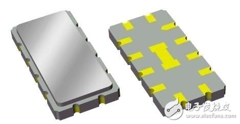
Below is an image illustrating the purpose and main parameters of a SAW filter:
Here are some key parameters of SAW filters:
- **Package**: LCCC (lead-free ceramic chip carrier), with the smallest size being 2.5 x 2 mm and weighing approximately 22 mg.
- **Center Frequency**: The average of two cutoff frequencies at a given relative insertion loss level (e.g., –3 dB).
- **Passband Width (Bandwidth)**: The frequency range between two cutoff points for a given insertion loss level.
- **Passband Ripple**: The variation in signal loss within the passband, typically defined by the difference between the highest peak and lowest valley.
- **Stopband Rejection**: The maximum level of unwanted signals in the stopband.
- **Rectangular Coefficient**: The ratio of bandwidths at different loss levels, often measured as the ratio of 40 dB to 3 dB bandwidth.
- **Group Delay Fluctuation**: The maximum difference in group delay across the passband.
- **Insertion Loss**: The amount of signal loss when the filter is inserted into the system. Early SAW filters had losses above 15 dB, but modern designs have reduced this to as low as 1–4 dB.
The operating frequency of a SAW filter depends on the width of the IDT (Interdigital Transducer) electrode. Narrower electrodes result in higher frequencies. With semiconductor processing at 0.35–0.42 μm, SAW filters operating at 2–3 GHz can be fabricated efficiently.
Here is another image showing a parameter table for a Japanese 920 MHz band SAW filter:
**Use of SAW Filters**
SAW filters are widely used for suppressing interference, filtering signals, and improving signal quality in communication systems. They effectively eliminate high-order harmonics, image signals, and parasitic noise, offering precise amplitude and phase characteristics that are hard to achieve with other types of filters.
In recent years, SAW filters have become smaller and lighter, with weights around 0.2 grams. Advances in crystal materials and fine processing techniques have pushed the upper frequency limit up to 2.5–3 GHz, making them ideal for anti-EMI applications.
In CATV systems, SAW filters enable adjacent-channel transmission with steep transition bands, doubling spectrum efficiency compared to traditional methods. Without SAW filters, TV receivers would struggle to maintain stability and reliability.
Initially, SAW filters were mainly used in audio-visual home appliances like televisions. However, with the rapid growth of the communication industry in the 1980s, they found new markets and saw a surge in demand. Today, over 600 million SAW filters are produced annually, with 430 million being small RF filters for mobile communication.
In mobile communication systems, both the transmitter and receiver require filters to function properly. These filters must have low insertion loss, high stopband rejection, good mirroring, and be compact and cost-effective.
Due to their performance advantages in terms of frequency range, size, and cost, SAW filters have become the preferred choice in mobile communication systems, outperforming ceramic and monolithic crystal filters. In wireless paging systems, SAW filters help improve signal reception, replacing older LC filters that were difficult to tune and lacked stability.
With the expansion of the internet, more users are accessing broadband services. However, traditional internet connections suffer from limited bandwidth and slow speeds. To address this, CATV networks are being used to deliver high-speed multimedia content, and SAW filters play a critical role in ensuring clear signal transmission.
Overall, the market potential for SAW filters is vast, driven by the growing demand for reliable, efficient, and compact filtering solutions in a wide range of applications.
FT06 Series Fused Terminal Connectors
Plug Terminal Block, Fuse Connector, H Type Terminal Block, Lighting Connector
Jiangmen Krealux Electrical Appliances Co.,Ltd. , https://www.krealux-online.com