The current transformer is an instrument that converts the primary side large current into the secondary side small current according to the principle of electromagnetic induction. The current transformer consists of a closed core and a winding. It has a small number of turns on the primary side winding, which is in the line of the current that needs to be measured.
Therefore, it often has all the current flowing through the line, and the number of turns on the secondary side is relatively large, which is connected in series between the measuring instrument and the protection circuit. When the current transformer is working, its secondary side circuit is always closed, so the measurement The impedance of the series coil of the instrument and the protection circuit is small, and the working state of the current transformer is close to the short circuit. The current transformer is measured by converting the primary side large current into the secondary side small current, and the secondary side is not openable. The entry introduces its working principle, parameter description, classification, introduction and so on.
Structural composition of current transformerThe current transformer is composed of a primary coil, a secondary coil, a core, an insulating support, and an outgoing terminal. The core of the current transformer is made up of silicon steel sheets. The primary coil is connected in series with the main circuit, and through the measured current I1, it generates alternating magnetic flux in the core, so that the secondary coil induces the corresponding secondary current I2. . If the excitation loss is neglected, then I1n1 = I2n2, where n1 and n2 are the turns of the primary and secondary coils, respectively. The current transformer has a current conversion ratio of K=I1/I2=n2/n1.
Since the primary coil of the current transformer is connected in the main circuit, the primary coil must be grounded to an insulation material compatible with the primary line voltage to ensure the safety of the secondary circuit and the human body. The secondary circuit is composed of a secondary coil of the current transformer, a meter, and a current coil of the relay in series. Current transformers can be roughly divided into two categories, current transformers for measurement and current transformers for protection.
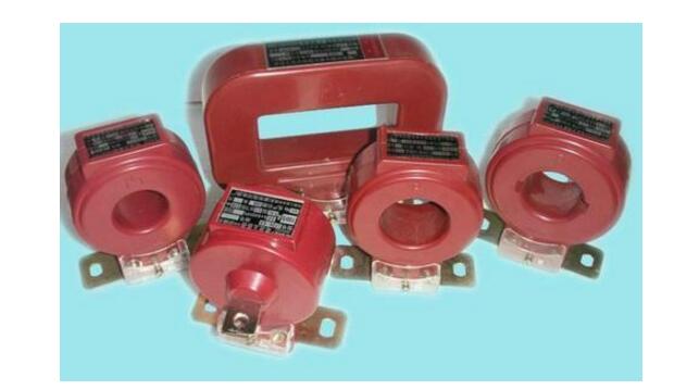
The principle of the current transformer is based on the principle of electromagnetic induction. Its primary winding often has all the current flowing through the line. When the current transformer is working, its secondary circuit is always closed, so the measuring instrument and the protection circuit are connected in series. The impedance is small and the operating state of the current transformer is close to a short circuit.
In an ideal current transformer, if the no-load current I0=0 is assumed, the total magnetomotive force I0N0=0, according to the law of conservation of energy, the primary winding magnetomotive force is equal to the secondary winding magnetomotive force, ie
I1NI=-I2N2
That is, the current of the current transformer is inversely proportional to its number of turns, and the ratio of the primary current to the secondary current I1/I2 is called the current ratio of the current transformer. When the secondary current is known, the primary current can be obtained by multiplying the current ratio, and the phasor of the secondary current differs from the phasor of the primary current by 1800.
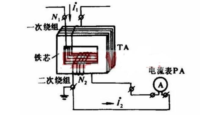
The rated current ratio is the ratio of the primary rated current to the secondary rated current (sometimes referred to as the current ratio). The rated current is expressed in the form of fractions that are generally not approximated. For example, if the primary rated current I1e and the secondary rated current I2e are 100 and 5A, respectively,
KI=I1e/I2e=100/5
The so-called rated current is that at this current, the transformer can operate for a long time without being damaged by heat. When the load current exceeds the rated current, it is called an overload. If the transformer is operated under long-term overload, it will burn its windings or shorten the life of the insulation.
2. level of accuracySince the current transformer has a certain error, the accuracy level of the transformer is divided according to the allowable error of the current transformer. The accuracy grades of domestic current transformers are 0.01, 0.02, 0.05, 0.1, 0.2.0.5, 1.0, 3.0, 5.0, 0.2S and 0.5S.
Current transformers of class 0.1 or above are mainly used for precision measurement in the laboratory, or as a standard for testing low-grade transformers. They can also be used with standard instruments to inspect instruments, so they are also called standard current transformers. User energy metering devices usually use 0.2-level and 0.5-level current transformers. For some special requirements (it is expected that the energy meter can be used between 0.05 and 6A, that is, between 1% and 120% of the rated current of 5A). Accurate measurement) Current transformers of 0.2S and 0.5S can be used.
3. Rated CapacityThe rated capacity of the current transformer is the apparent power S2e consumed when the rated secondary current I2e passes through the secondary rated load Z2e, so
S2e=I2e2Z2e
In general, I2e = 5A, therefore, S2e = 52Z2e = 25Z2e, and the rated capacity can also be expressed by the rated load impedance Z2e.
When the current transformer is in use, the total impedance of the secondary connection line and the instrument current coil cannot exceed the rated capacity specified on the nameplate and not less than 1/4 of the rated capacity to ensure its accuracy. The rated secondary load of the manufacturer's nameplate calibration is usually expressed in rated capacity, and its output standard values ​​are 2.5, 5, 10, 15, 25, 30, 50, 60, 80, 100V·A, etc.
4. Rated voltageThe rated voltage of the current transformer refers to the maximum voltage (effective value) that the primary winding can withstand for a long time to the ground. It only describes the insulation strength of the current transformer, and has nothing to do with the rated capacity of the current transformer. It is marked after the current transformer model. For example, LCW-35, where "35" refers to the rated voltage, which is in kV.
5. Polarity signIn order to ensure correct wiring of the measurement and calibration work, the terminals of the primary and secondary windings of the current transformer shall be marked with a polarity mark.
(1) The primary end of the primary winding is labeled L1 and the end is labeled L2. When the multi-quantitative primary winding has a tap, the first end is marked as L1, and is marked as L2, L3... from the first tap.
(2) The primary end of the secondary winding is labeled K1 and the end is labeled K2. When the secondary winding has a center tap, the head end is marked as K1, and the following marks are sequentially marked as K2, K3... from the first tap.
(3) For current transformers with multiple secondary windings, the numbers should be added before the exit line mark “K†of each secondary winding, such as 1K1, 1K2, 1K3... „2K1, 2K2, 2K3... .
(4) The arrangement of the glyphs should be such that when a primary current flows from the L1 end to the L2 end, the secondary current flows out from K1 and flows back to K2 via the external circuit.
From the point of view of the same polarity terminal of the primary and secondary windings of the current transformer, the directions of the currents I1 and I2 are opposite. Such a polarity relationship is called a polarity reduction, and vice versa. Current transformers are generally expressed in terms of reduced polarity.
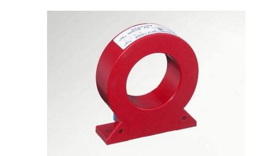
1. One of the functions of the current transformer is for measurement, which is often used to charge or measure the current level of the device in operation. In the measurement of large alternating current, in order to facilitate the measurement of the instrument and reduce the risk of directly measuring the high voltage, it is often necessary to use a current transformer to convert it into a more uniform current, where the current transformer starts. The role of converter and electrical isolation. The current transformer converts the high current into a low current proportionally according to requirements. For the measurement, the primary side of the current transformer is connected to the primary system, and the secondary side is connected to the measuring instrument or the relay protection device.
2. The second function of the current transformer is for protection, often used in conjunction with the relay device. When the line is short-circuited or overloaded, the current transformer sends a signal to the relay device to cut off the fault circuit, thereby achieving Protect the safety of the power supply system. The protection current transformer is different from the current transformer for measurement, and it can work effectively only when the current is several times or several times larger than the normal current, and it requires reliable insulation and sufficient accuracy limit. Coefficient, sufficient thermal stability and dynamic stability.
1KW-8KW Power Inverter
Use double MCU design,the product provides different charge voltages and charge currents to realize charge management for batteries of different types.Its mains supply preferred mode,energy--saving mode and battery preferred mode are all settable,thus making it easy to meet users' different application needs.It has an LCD to show operation status.It is widely applied to families,schools,streets,frontier defense,pasturing areas,industrial equipment,military vehicle--borne equipment,ambulances,police cars,ships,ect.
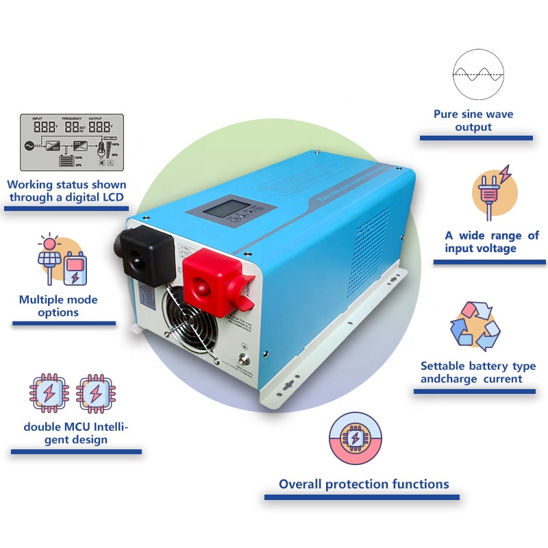
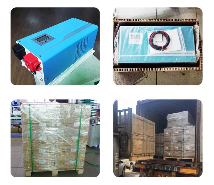
Nkm Hybrid Inverter With Mppt Charge,Inverter Power Inverter,Hybrid Inverter Charger,Hybrid Grid Tie Inverter
suzhou whaylan new energy technology co., ltd , https://www.whaylan.com