This technical document provides detailed pin function descriptions for a complex integrated circuit commonly used in video and audio systems. Each pin serves a specific role, contributing to the overall functionality of the device. Below is a breakdown of the key pins and their functions:
1. SVIDEO – 4.6V terminal brightness input
2. MUTE – 0V mute output
3. KEY in – 0.3V button matrix input
4. UP Dvss – 0V Ground
5. RESET – 4.8V reset pin
6. X in – 2.1V crystal input
7. X out – 0.9V crystal output
8. TEST – 0V test foot
9. UP Dvvd – 4.8V +5V power supply
10. UP Dvss – 0V Grounding Feet
11. TV AGND – 0V Grounding foot
12. FBP – 1.0V retrace pulse input
13. Hout – 1.8V line excitation output
14. HAFC – 6.4V line sync signal separation filter
15. Vsaw – 4.0V Normal Sawtooth Filter
16. Vout – 4.6V Field Excitation Output
17. Hvcc – 9.2V line start power
18. NC – 0.9V empty foot
19. Cb in – 9.9V BY signal input
20. Y in – 9.7V Y signal input
21. Cr in – 9.9V RY signal input
22. VD AND – 0V ground
23. C in – 9.8V Chroma signal input
24. V2 in – 9.8V video 2 signal input
25. TV DVCC – 3.4V Luo Ji power end
26. VI in – 2.0V video input
27. ABCL – 3.8V Automatic Brightness Color Control Terminal
28. AU out – 3.4V audio signal output
29. IF VCC – 8.7V IF +9V power supply
30. TV out – 3.5V video signal output
31. SIF out – 1.8V audio signal output
32. EXT AU in – 3.1V External audio signal input
33. SIF in – 2.1V audio signal input
34. DC NF – 2.0V DC Negative Feedback External Capacitor
35. PIF PLL – 2.4V PIF Phase-Locked Loop
36. IFVCC – 4.4V +5V power supply pin (IF)
37. Reg Fil – 2.0V External Capacitor Filter
38. Deempha – 4.2V SIF to aggravate
39. IF AGC – 1.5V IF AGC Filter
40. IF GND – 0V Ground (IF)
41. IF in – 0V IF signal input
42. IF in – 0V IF signal input
43. RF AGC – 1.6V RI AGC output
44. TV YC VCC – 4.4V +5V power supply
45. Monitoy out – 1.7V Monitoring output
46. BLACK DET – 2.4V Black Level Detection
47. Chroma PLL – 1.7V Color Phase Locked Loop
48. IK in – 0V cathode detection current input
49. RGB VCC – 8.7V RGB power supply
50. Rout – 2.5V red primary signal output
51. Gout – 2.5V green primary signal output
52. Bout – 2.5V blue primary signal output
53. TV AGND – 0V Ground
54. UP AGND – 0V Grounding Foot
55. UP AVDD – 4.8V +5V power supply
56. BAND – 4.8V Band Control
57. SDA – 4.6V I2C serial data in/out
58. SCL – 4.6V I2C serial data in/out
59. VOL – 2.3V Volume Control
60. VT – 4.6V Tuning Control Output
61. BAND – 0.1V Band Control 1
62. HSYNC – 3.4V line sync pulse input
63. RMT in – 4.2V Remote Signal Input
64. power – 0.1V power standby control input
This detailed pin configuration is essential for developers, engineers, and technicians who are working with advanced video processing or audio systems. Understanding each pin's purpose ensures proper integration and operation of the device within larger circuits.
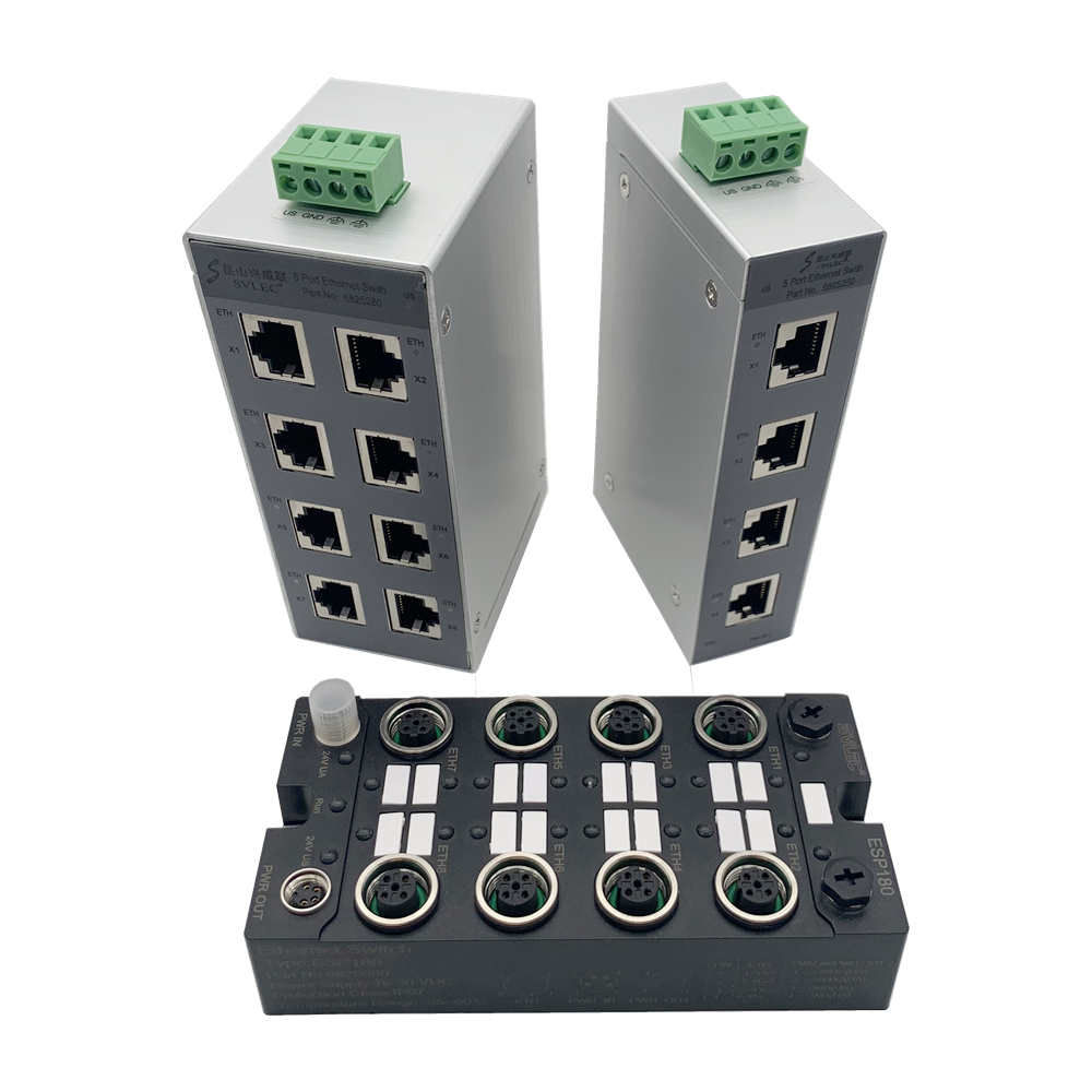
SVLEC Ethernet switches have 5 port and 8 port , IP 20 series have 5 or 8 RJ45 socket , with 100/1000 Mbps transmission speed and POE support , can be mounted on the rail . IP67 series have 8 M12 D code female port , with 10/100 MBit/s , wall mount and panel installation can widely used in CNC machines , Logistics and other areas .

Ethernet Switches,8 Port Ethernet Switch,5 Port Ethernet Switch,100Mbps Ethernet Switch, IP67 ethernet switch
Kunshan SVL Electric Co.,Ltd , https://www.svlelectric.com