Ankerui Electric Co., Ltd. Shanghai Jiading
Abstract Ankerui residual current type electrical fire monitoring system conducts electrical fire monitoring of low voltage distribution systems in shopping malls, hotels, airports, banks, hospitals, and factory buildings through ARCM residual current electrical fire monitoring devices or digital residual current transformers. . Through the introduction of the project of Guizhou Liyang Aviation Power Co., Ltd.'s electrical fire monitoring system, this article focuses on the functions and significance of the Acrel-6000 electrical fire monitoring system.
Keywords: residual current transformer, electrical fire, monitoring system, Li Yang Aviation, Ankerui
1 Introduction
AVIC Guizhou Liyang Aero Engines (Group) Co., Ltd. (abbreviated as AVIC Liyang) is one of the backbone manufacturers of aero engines in China and is a national I type enterprise. The company is striving to implement the development strategy of “Two Harmony, Three New, Five Chemicals, and One Tera Yuan†by AVIC, accelerating the pace of reform and development. It has purchased 2000 mu of land in the Guiyang Hi-tech Development Zone and spent RMB 4.5 billion to start construction of Guiyang Aero Engine. Industry Base. This project is designed for the electrical fire monitoring of the new factory buildings.
2. System Requirements Analysis
The electrical fire monitoring system should be able to accurately monitor the faults and abnormal conditions of the electrical lines, discover the fire hazards of electrical fires, and promptly alert relevant personnel to eliminate these hidden dangers and prevent electrical fires.
3. Reference standards
The system complies with the People's Republic of China national standard GB14287.1-2005 "Electrical fire monitoring system - Part 1: Electrical fire monitoring equipment."
4. System structure
Acrel-6000 electrical fire monitoring system is an independent research and development by the company to receive the residual current electrical fire detectors and other field equipment signals, in order to achieve the protection of the electrical circuit alarm, monitoring, control, management of the computer running on the industrial level Hardware/software system. This system is applied to fire control centers in large shopping malls, living quarters, production bases, office buildings, shopping malls, hotels, etc., and remotely measure, remotely adjust, remotely control, and remotely locate the detectors scattered in the building to facilitate monitoring and management. The system uses a standard Modbus field bus to connect detectors with communication functions. When the detected parameters in the field protection circuit exceed the alarm setting value, it can send alarm signals, control signals, can indicate the alarm location and save the alarm. information.
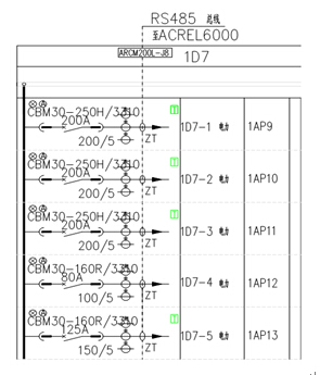
The project site of Guizhou Liyang Aviation Power Co., Ltd. is a processing plant. No. 1 and No. 2 low-voltage power distribution rooms have installed four ARCM200L electrical fire detectors and three ARCM200L electrical fire detectors, respectively monitoring the low pressure distribution of No.1 and No.2. The distribution loops of the power distribution cabinets in the electric room. The on-site electrical fire detectors are bus-connected to the Acrel-6000 wall-mounted electrical fire monitoring system. This system has the advantages of convenient installation and transportation, high cost performance, and easy maintenance.
The main equipment of Acrel-6000 electrical fire monitoring system is as follows:
1 Main Control Unit: Industrial Tablet PC with Touch Screen, WinCE Operating System
2 I/O: Smart DCMOD module developed by built-in company, with multiple input and output
3 sound and light alarm: built-in speaker, LED indicator
4 Backup power: Maintenance-free batteries with 2 12V/7.2Ah
Host panel component layout and function description
1: Alarm indicator (red): When the device receives the alarm signal from the detector, the alarm indicator is on.
2: Fault indicator (yellow): When the system has a fault (such as communication fault, power supply fault, etc.), the fault indicator is on.
3: Running indicator (green): The indicator is always on when the device is operating normally.
4: Main power indicator (green): When the main power supply is normal, the monitoring device is powered by the main power supply, and the main power indicator is always on.
5: Standby power indicator (green): When the main power supply is undervoltage or faulty, the monitoring device is powered by the standby power supply. The standby power indicator is always on.
This system is distributed using a computer distributed network structure, as shown in the following figure:
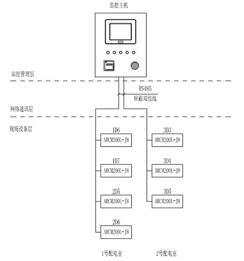
1) Station control management
Station management The management personnel of the electrical fire monitoring system are the direct windows of human-computer interaction and the top part of the system. Mainly by the system software and necessary hardware devices, such as industrial-grade tablet computers, micro-printers, UPS power supply and other components. The monitoring system software has a good human-computer interaction interface, calculates, analyzes, and processes various types of data on the site, and responds to on-site operations with graphics, digital displays, sounds, and indicators.
Monitoring host: used for data acquisition, processing and data forwarding. Provides data interfaces within or outside the system for system management, maintenance, and analysis.
Printer: System calls to print or automatically print graphics, reports, alarm records, etc.
UPS: Ensure the normal power supply of the computer monitoring system. When the power supply problem occurs in the entire system, ensure the normal operation of the station control and management equipment.
The host of electrical fire monitoring system is installed in the fire control room of the factory building.
2) Network communication layer
Communication medium: The system mainly uses shielded twisted pair to RS485 bus to connect to the fire control room monitoring host to achieve real-time communication between the field device and the host computer. The communication line was laid along the weak bridge in the plant area to ensure the quality of communication.
3) Field device layer
The field device layer is a data acquisition terminal, mainly ARCM200L electrical fire detectors and AKH-0.66L series leakage current transformers. The ARCM200L can monitor 8 leakage currents. Each channel has the functions of disconnection and short circuit detection. With the event storage function, the alarm can record the time, type, and parameter of the alarm. According to the alarm record, it can analyze the situation of the electricity in the site and eliminate it. Faults are provided on the basis of field bus communication technology, PC management software can always monitor the operation of the scene, timely detection of alarm information. The standard MODBUS protocol can be connected with various standard systems; it has high integration, networking, and high intelligence.
5. System function
This set of PC software Acrel-6000 electrical fire system. Mainly has the following function characteristic: The friendly man-machine contact surface, may collect the residual current data of the scene equipment real-timely and regularly, and has the warning prompt sound and light alarm and so on the function. The customer can set the leakage current alarm value according to the actual needs. When the alarm fault is removed, it can be reset remotely. The system can record alarm events, dates, alarm values, and over-line values ​​and generate reports that can print alarm event records.
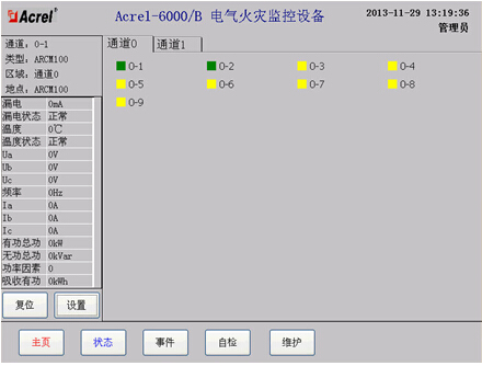
1) Monitor the main interface

On-site ARCM200L electrical fire detector acquisition data uploaded to the interface, the customer can modify the name of the circuit according to need, can display the corresponding cabinet real-time residual current value, the data can be periodically updated. When the measured value of the residual current is greater than the alarm setting, the system alarm status indicator will flash automatically. The alarm prompt scroll bar at the bottom of the interface will automatically prompt the name of the alarm loop, which is convenient for the operator to check and handle the fault.
2) Detector communication failure information prompt interface
This interface mainly realizes the remote adjustment function. The operating personnel can query the alarm value of the residual current in the corresponding circuit in the parameter setting report, and set the alarm value of the residual current crossing line according to the actual needs of the site. At the same time, it can also reset the alarm instrument remotely. When the fault alarm is released, press the reset button to perform remote reset to facilitate the use of the user.
3) Event record query interface
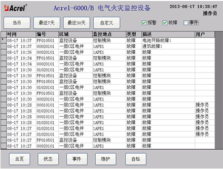
With event storage function, the alarm can record the time, type, parameter and alarm value of the alarm. According to the alarm record, it can analyze the cause of the fault and provide the basis for eliminating the fault. The alarm record can be printed.
6. Conclusion
With the development of smart buildings and the widespread use of electricity, people have become more aware of security awareness. The installation of a leakage fire system in public buildings is an inevitable trend of intelligent construction. The electrical fire system is conducive to discovering hidden dangers and dealing with hidden dangers in time. It is of great significance to prevent fires from happening. Since the system was put into operation, many hidden dangers have been discovered and rectified, which provided a scientific basis for the project's fire control management and received favorable comments from customers.
references
[1]. Ren Cheng, Zhou Zhongzhong. Principles and Application Guide for Digital Meters for Electric Power Measurement [M]. Beijing. China Electric Power Press, 2007. 4
[2].Zhou Zhong. Application of Electric Power Meters in Energy Metering of Large-scale Public Buildings [J]. Modern Building Electric 2010. 6
About the author: 牟芸 Female, Ankerui Electric Co., Ltd., the main research direction for the motor protection energy-saving control, mobile phones, landline, QQ