The access control system is commonly referred to as the entrance and exit control system. It serves as a critical tool for managing the movement of people and goods within a secured environment. In typical design and application scenarios, the system's control is primarily focused on authorized personnel. According to the Ministry of Public Security's GA/T 394-2002 "Technical Requirements for Access Control System" and the national standard GB50396-2007 "Engineering Design Specification for Entry and Exit Control Systems," the system must include four essential functions: release, rejection, recording, and alarm. As an active prevention system in security technology, it not only identifies and verifies individuals or items but also quickly makes decisions to either "release" or "reject" access. All entry and exit activities are recorded and stored for future reference. Moreover, if the system is compromised, it should have built-in protection and alarm mechanisms to alert users.
 According to GB50396-2007, five specific provisions are mandatory and must be strictly followed. However, in real-world projects, these requirements are often overlooked, leading to serious flaws in the system’s functionality and security.
Equipment selection and anti-destruction and anti-technical opening capabilities
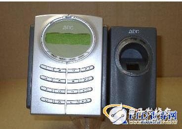
When designing an access control system, equipment must be selected based on the project’s required safety level. This includes evaluating the system’s protection capability, especially its resistance to physical damage and technical tampering. The national standard GB50396-2007 categorizes equipment protection into three levels: A, B, and C, from lowest to highest. It's important to note that many people confuse "anti-vandal" with "anti-device destruction." The correct understanding involves assessing whether the entrance can remain secure even if the equipment on the protective surface is damaged. For example, one card reader might be destroyed in just one minute, yet the entrance remains locked for 30 minutes. Another device may appear robust but could be opened in under a minute after being damaged. This highlights the importance of choosing devices that meet both "anti-vandal" and "anti-technical opening" standards. Some fingerprint readers, for instance, have exposed RESET buttons that can be easily manipulated, potentially erasing all stored data.
Control equipment installation location and system's own security level
GB50396-2007 clearly outlines where control equipment should be installed. Article 6.0.2 specifies that non-coded signal-based control equipment must be placed in the corresponding controlled area, same-level controlled area, or higher-level controlled area of the entrance. In most cases, card readers are installed outside the controlled area, while controllers and power supplies are located inside. However, when using multi-door controllers—devices that manage multiple doors—it becomes more complex to determine their placement, which directly affects the system’s overall security.
According to GB50396-2007, five specific provisions are mandatory and must be strictly followed. However, in real-world projects, these requirements are often overlooked, leading to serious flaws in the system’s functionality and security.
Equipment selection and anti-destruction and anti-technical opening capabilities
When designing an access control system, equipment must be selected based on the project’s required safety level. This includes evaluating the system’s protection capability, especially its resistance to physical damage and technical tampering. The national standard GB50396-2007 categorizes equipment protection into three levels: A, B, and C, from lowest to highest. It's important to note that many people confuse "anti-vandal" with "anti-device destruction." The correct understanding involves assessing whether the entrance can remain secure even if the equipment on the protective surface is damaged. For example, one card reader might be destroyed in just one minute, yet the entrance remains locked for 30 minutes. Another device may appear robust but could be opened in under a minute after being damaged. This highlights the importance of choosing devices that meet both "anti-vandal" and "anti-technical opening" standards. Some fingerprint readers, for instance, have exposed RESET buttons that can be easily manipulated, potentially erasing all stored data.
Control equipment installation location and system's own security level
GB50396-2007 clearly outlines where control equipment should be installed. Article 6.0.2 specifies that non-coded signal-based control equipment must be placed in the corresponding controlled area, same-level controlled area, or higher-level controlled area of the entrance. In most cases, card readers are installed outside the controlled area, while controllers and power supplies are located inside. However, when using multi-door controllers—devices that manage multiple doors—it becomes more complex to determine their placement, which directly affects the system’s overall security.
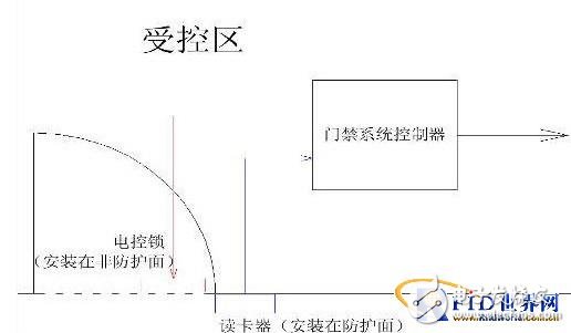 As shown in Figure 1, a standard single-door access control system typically places the controller inside the controlled area. But when multiple doors are involved, the controller’s location becomes a critical factor. If two zones require different security levels, placing the controller in one zone may leave the other vulnerable. This is because most controllers use non-encoded signals to operate electronic locks, making them susceptible to attacks. Therefore, careful planning is necessary to ensure the controller is positioned in the most secure location possible.
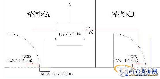 Figure 2 illustrates a two-door controller used for Zones A and B. If both zones are at the same security level, the controller can be placed in either. However, if they are at different levels, the controller’s placement creates a vulnerability. The weakest point is usually the connection between the controller and the lock, which can be targeted by intruders.
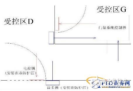 For higher security zones, such as G (the highest-level core laboratory), the controller should be placed in the most secure area. This ensures that even if one part of the system is compromised, the core areas remain protected.
In a comprehensive system like the one shown in Figure 4, different zones (A, B, E) are managed by a shared multi-door controller. However, independent zones (C, D) require separate controllers due to their unique security needs. Zone D, connected to the lab, is controlled from the highest-level G zone, ensuring that the system’s integrity is maintained across all levels. This approach ensures that only authorized personnel can access sensitive areas, maintaining the system’s effectiveness and reliability.
For higher security zones, such as G (the highest-level core laboratory), the controller should be placed in the most secure area. This ensures that even if one part of the system is compromised, the core areas remain protected.
In a comprehensive system like the one shown in Figure 4, different zones (A, B, E) are managed by a shared multi-door controller. However, independent zones (C, D) require separate controllers due to their unique security needs. Zone D, connected to the lab, is controlled from the highest-level G zone, ensuring that the system’s integrity is maintained across all levels. This approach ensures that only authorized personnel can access sensitive areas, maintaining the system’s effectiveness and reliability.
According to GB50396-2007, five specific provisions are mandatory and must be strictly followed. However, in real-world projects, these requirements are often overlooked, leading to serious flaws in the system’s functionality and security.
Equipment selection and anti-destruction and anti-technical opening capabilities
When designing an access control system, equipment must be selected based on the project’s required safety level. This includes evaluating the system’s protection capability, especially its resistance to physical damage and technical tampering. The national standard GB50396-2007 categorizes equipment protection into three levels: A, B, and C, from lowest to highest. It's important to note that many people confuse "anti-vandal" with "anti-device destruction." The correct understanding involves assessing whether the entrance can remain secure even if the equipment on the protective surface is damaged. For example, one card reader might be destroyed in just one minute, yet the entrance remains locked for 30 minutes. Another device may appear robust but could be opened in under a minute after being damaged. This highlights the importance of choosing devices that meet both "anti-vandal" and "anti-technical opening" standards. Some fingerprint readers, for instance, have exposed RESET buttons that can be easily manipulated, potentially erasing all stored data.
Control equipment installation location and system's own security level
GB50396-2007 clearly outlines where control equipment should be installed. Article 6.0.2 specifies that non-coded signal-based control equipment must be placed in the corresponding controlled area, same-level controlled area, or higher-level controlled area of the entrance. In most cases, card readers are installed outside the controlled area, while controllers and power supplies are located inside. However, when using multi-door controllers—devices that manage multiple doors—it becomes more complex to determine their placement, which directly affects the system’s overall security.
As shown in Figure 1, a standard single-door access control system typically places the controller inside the controlled area. But when multiple doors are involved, the controller’s location becomes a critical factor. If two zones require different security levels, placing the controller in one zone may leave the other vulnerable. This is because most controllers use non-encoded signals to operate electronic locks, making them susceptible to attacks. Therefore, careful planning is necessary to ensure the controller is positioned in the most secure location possible.
Figure 2 illustrates a two-door controller used for Zones A and B. If both zones are at the same security level, the controller can be placed in either. However, if they are at different levels, the controller’s placement creates a vulnerability. The weakest point is usually the connection between the controller and the lock, which can be targeted by intruders.
For higher security zones, such as G (the highest-level core laboratory), the controller should be placed in the most secure area. This ensures that even if one part of the system is compromised, the core areas remain protected.
In a comprehensive system like the one shown in Figure 4, different zones (A, B, E) are managed by a shared multi-door controller. However, independent zones (C, D) require separate controllers due to their unique security needs. Zone D, connected to the lab, is controlled from the highest-level G zone, ensuring that the system’s integrity is maintained across all levels. This approach ensures that only authorized personnel can access sensitive areas, maintaining the system’s effectiveness and reliability.Zirconia Ceramics,Zirconia Engineering Components,Zirconia Precision Parts,Zirconia Wear Resistant Parts
Yixing Guanming Special Ceramic Technology Co., Ltd , https://www.guanmingceramic.com