According to the International Energy Report, the energy consumption of electronic motors in 2006 was 46% of the total global energy consumption, equivalent to 6040 Mt CO2 emissions. This has led to the need for motor drive manufacturers to add advanced control features and tools to optimize system energy efficiency. The new motor drive ecosystem that optimizes energy efficiency in factory production systems has been widely recognized around the world. For Europe, thanks to the energy-saving policy, industrial electricity consumption shows a downward trend of 1% per year.
The most common places in the factory where motors are used are electric pumps, fans, compressors and conveyors, and most of these motors are standard products in these applications. Small motors (less than 0.75 kW) used in small machines account for 90% of global stock, but the motor consumes less than 10% of the total. However, medium-sized (0.75 kW to 350 kW) industrial motors account for almost 70% of global motor energy consumption. In a typical application, only 50% of system energy is converted to useful mechanical energy, which has attracted the attention of global energy regulators and manufacturers. Over the past few years, regulators in the United States, China, Europe, and other regions have introduced minimum energy performance standards (MEPS). High-quality motors are now rated for energy efficiency from 80% at the lowest power consumption range to 96% at the highest, so manufacturers are looking for energy-saving alternatives to motors.
Figure 1 depicts the main elements of an automated machine or process in a modern factory. This approach provides a new way to optimize machine operation and process, taking energy efficiency and productivity to new heights.
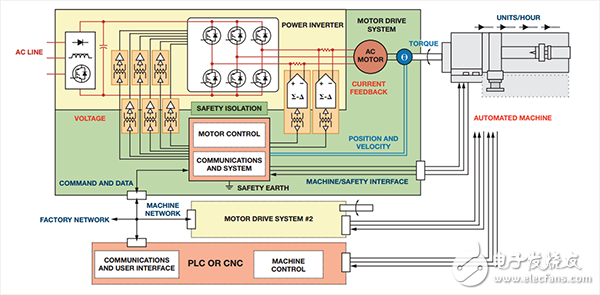
The efficiency of the motor and the overall production process are determined by multiple control layers.
The first control layer regulates the switching sequence of the power inverter, controlling the motor voltage and current as well as the maximum torque productivity.
The second layer is the position and speed controller that operates the machine efficiently.
In a process device, it can drive an optimal pump flow rate; in an automation device, it can be a sequence of speed or position commands that perform an assembly function. In the latter case, the response time of the speed control is more important to the machine controller than the torque productivity. The importance of the communications and system layers is growing, as multiple motors are now synchronized via high-speed data networks and connected to the factory network. The process manager can turn on the machines sequentially when needed, rather than having them wait in idle mode. Networked security features enable efficient start and stop of the device, minimizing downtime. Factory managers track the operation of the motor drive and diagnose the data to improve process energy efficiency and reliability.
Efficient torque generation: Algorithm and EthernetMotor efficiency is a function of the torque produced per ampere at any given speed and terminal voltage. The electronic motor generates torque by a force that attempts to pull its internal magnetic field to an aligned position. In the AC motor of Figure 2, these forces are generated by the interaction of the stator and rotor fields. When the stator current is synchronized with the rotor motion, the AC motor produces a constant torque that maintains a misaligned state of the continuous field. The AC motor speed is directly related to the motor current frequency and requires a variable frequency voltage source for speed control. When the magnetic field alignment error between the rotor and the stator reaches the maximum, the efficiency is the highest. Motor efficiency also depends on the motor structure, especially the rotor field structure. In asynchronous induction motors (AIM), current flows through the rotor and stator windings, and some of the minimum stator current is consumed to magnetize the core. Permanent magnet synchronous motors (PMSM) are more efficient because they do not require any current to magnetize the rotor field. Ultra-high efficiency internal permanent magnet (IPM) motors are capable of generating additional torque with a prominent core structure.
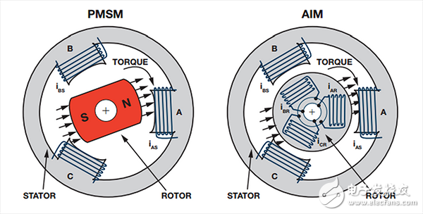
All of the above motors are used in the industry, depending on power and application requirements, but because of their simple structure and ease of use, asynchronous induction motors are by far the most commonly used motors. Permanent magnet synchronous motors have a high torque-to-weight ratio and their low inertia rotor construction makes them ideal for high dynamic control applications in automated equipment. However, the AIM can be started when the three-phase AC line is directly connected, and the speed can be controlled using a simple frequency inverter. In the past, instead of focusing on efficiency, it is common to connect a fan, pump or compressor directly to the AC line and control the process via a damper, valve or simple on/off. At 50% speed, open loop frequency control reduces the power consumption of the centrifugal pump to less than 20% of full power; while using on/off control to reduce the flow rate to 50%, the power consumption is 50% of full power. This increase in system efficiency has prompted manufacturers to retrofit existing inverters for fixed speed motor applications. Recently, advanced algorithms can adjust the rotor magnetic field by fine-tuning the stator voltage to optimize efficiency. Drive manufacturers are now offering standard drive boxes that can be configured for a variety of motor types and types.
The latest analog and digital signal processing equipment introduces advanced control functions even in cost-sensitive inverter applications. The estimation algorithm calculates the angular position of the rotor magnetic field by measuring only the stator current and voltage. These sensorless control algorithms simplify the deployment of high-efficiency IPM motors and maximize the processing efficiency of applications such as compressors and conveyors. Higher power applications such as winding machines or large pumps still tend to use induction motors, but typical efficiencies for 500 kW motors can be as high as 96%. The algorithms built into these drives typically optimize motor efficiency and monitor the operation of the drive. In general, these drives use a serial fieldbus connection that allows the local PLC to record operational and diagnostic data. A growing trend is to connect drives to the plant network using industrial Ethernet protocols such as Ethernet/IP or Modbus TCP to improve efficiency by coordinating the operation of multiple drives.
Efficient motion control: precise isolation and communicationAccurate motion control combined with precise communication timing reduces machine cycle times and reduces the energy used to produce each component. This is important in automated systems where machine productivity and quality are often more important than motor energy efficiency due to capital investment in equipment. Drive manufacturers support automation applications with PMSM servo motors and drives; these motors and drives are designed for fast response and high accuracy in speed and position control.
The fast control processor with precise voltage drive and current feedback provides smooth dynamic torque control. High voltages and currents in power inverters are a challenge for circuit designers because they must meet stringent electrical safety standards. High-speed magnetic isolation technology supports safe isolation of analog and digital signal voltages without sacrificing speed or accuracy performance. The precision analog-to-digital converter built into the encoder provides position feedback up to 24-bit resolution for high dynamic speed control down to 1 RPM. This level of performance can support automation applications such as multi-axis milling of precision machine components, assembly of fine geometry integrated circuits, or injection molding of mobile phone components. In addition to control accuracy, motor motion timing needs to be tightly synchronized, because timing errors directly lead to trajectory errors in multi-axis position control. Synchronous Industrial Ethernet protocols such as PROFINET and EtherCat use a modified Ethernet network interface to support real-time data synchronization with clock jitter as low as 1 μs. These network interfaces support all two simultaneous motion controls for high productivity in production system management and factory network connectivity.
Engineering efficiency: quick customizationModeling tools allow drive companies to quickly customize control algorithms for end applications without the need for extensive trial production and error tuning at the factory.
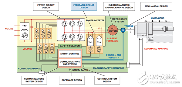
Automated machines are complex interconnected systems that require the support of an interdisciplinary engineering team. Figure 3 shows only some of the key design features required to support the development of automation equipment. In general, many of these engineers work in different companies, so different suppliers in the supply chain must support the integration of the designer. Modeling tools from companies such as MathWorks support complete system models, including state control, motion algorithms, motor and machine loads. Special electromagnetic and mechanical design tools can generate behavioral models of AC motors and machines, increasing the accuracy of the system model. Although the entire design process cannot be fully automated, the number of prototyping can be drastically reduced. New motor or machine control algorithms can be developed and tested on the simulation platform prior to prototyping. Automated code generation tools allow rapid deployment of control algorithms on the test platform. Each design iteration provides new data to improve the accuracy of the system model. Automatically generated control code plus validated system application code can be used in production drive systems. As a result, drive companies can quickly deploy new control features optimized for specific applications to optimize energy efficiency and automation productivity.
More and more industrial and instrumentation applications require precision converters to achieve precise control and measurement of various processes. In addition, these end applications require greater flexibility, reliability, and feature set while reducing cost and board space. Component manufacturers are addressing these challenges and have introduced a range of products to meet system designers' requirements for current and future designs. As described herein, there are a number of ways to select suitable components for precision applications, each with advantages and disadvantages. As the accuracy of the system increases, people need to pay more attention to the selection of suitable components to meet the application requirements.
What is Flexible PCB?
Flexible PCB`s are now being used in place of traditional FR4 in a large number of different applications,Benefits include solving interconnecting problems, reduction of weight, reduction of space and reduced assembly costs. Flexible applications can be dynamic flexing (designed for flexing or stress over a period of time at elevated temperatures) or flex & stay applications (designed for flexing once and being secured into place).
Quickly Turn flexible Service.
Not only do we offer flexible PCBs for fast production, we can also provide flex PCB prototypes to see your custom designs before a big shipment is created. Royal Circuits flex and rigid-flex capabilities are designed to meet a variety of circuit board needs from single or double-sided circuitry to multilayer technology. We also offer different material substrates and adhesives, as well as surface finishes and treatments. Stiffeners can also be added for reinforcement.
Full Product Lines of Flexible Circuits
Our product lines includes single sided flex circuits, dual access flexible PCB , double sided flexible circuit, multi-layer Flex circuits and rigid-flex circuits. We work shoulder by shoulder with our customers to achieve the quality, delivery, and cost objectives for their projects of Flex PCB ( FPCB). We are a flexible printed circuit source that can accommodate your customized program initiatives such as ship to stock.
Flex PCB,Flex PCB Board,Ribbon Flex PCB,Aluminum Flex Led PCB
Storm Circuit Technology Ltd , https://www.stormpcb.com